
Leaks usually trace back to aging seals, thermal cycling, corrosion, mechanical stress, poor installation, or deferred maintenance. A U.S. Bureau of Reclamation guide ties gasket leaks to wrong torque, wrong gasket type or size, poor surface preparation, and hardening with age and temperature extremes.
This article covers how the valve works, how to find the real leak source, how qualified crews approach repair, when replacement makes more sense, and when a leak-sealing specialist belongs in the conversation.
Key Takeaways
- Common leak points: gasket, stem packing, body, seat, threaded or flanged connection, and tank interface.
- Gasket, packing, or connection leaks may be repairable; cracked bodies or damaged threads usually mean replacement.
- Diagnose before tightening or replacing anything.
- Specialist leak sealing can cut disassembly and downtime when conditions allow.
What Is a Transformer Oil Drain Valve?
A transformer oil drain valve is a controlled outlet on an oil-immersed transformer tank. Crews use it to drain, sample, filter, or otherwise manage insulating oil. Some designs combine drain and sampling functions in one assembly.
The valve stays closed in normal service to keep oil in the tank. It opens only during approved maintenance or oil processing.
An oil-immersed transformer has its core and coil immersed in insulating liquid, which provides electrical insulation and heat transfer. ASTM describes mineral insulating oil as serving exactly those insulation and cooling roles. Keeping the correct level and condition matters because moisture ingress can reduce dielectric strength.
One caution: oil around the valve doesn't always come from the valve. It can migrate from:
- A nearby flange or weld
- A sampling port or gasket
- A component higher up on the tank
Source identification comes first.
Common Problems With Transformer Oil Drain Valves and Why They Fail
Most drain valve leaks follow recognizable patterns, but oil travels across tank surfaces and makes the apparent source misleading. Residue left from shipping or manufacturing can also mimic an active leak.
Threaded or Flanged Connection Leaks
- Symptoms: wetness or pooling at the connection, a deteriorated gasket, seepage that changes with temperature.
- Causes: loose or uneven hardware, gasket compression loss, incompatible sealing material, damaged threads, contamination during installation.
TDS notes that extra bolt tightening rarely stops a failed 4-bolt flapper valve flange gasket leak.
Stem, Packing, or Operating Mechanism Leaks
- Symptoms: oil at the stem or handwheel while the body and outlet stay dry.
- Causes: aged packing or O-rings, stem wear, corrosion, excessive operating force, improper adjustment.
Packing failure is common on 4-bolt flapper and 8-bolt butterfly valve stems. Once packing deteriorates, tightening the nut can't restore compression.
Body, Seat, Plug, or Ball Won't Seal
- Symptoms: seepage from the outlet after closure, no full shutoff, a stiff valve.
- Causes: internal wear, contamination on sealing surfaces, corrosion, mechanical damage, distorted parts.
Cracked, Corroded, or Damaged Valve
Leakage through the body, visible cracks, deep corrosion, distorted fittings, or a leak that returns after seal replacement points to structural damage. That calls for replacement or an engineered repair decision, not more tightening.
Leak From the Tank Interface or a Neighboring Part
Oil from a tank weld, radiator connection, sampling port, or bushing area can collect around the drain valve. Clean the area, trace the highest wet point, and use an approved detection method.
In one TDS example on a 4-bolt flapper valve, visual inspection couldn't tell whether the flange gasket, the stem, or both had failed. Detector powder darkened at both.

What's at Stake
Left unaddressed, drain valve leaks can cause:
- Lost insulating oil, plus moisture or contamination ingress
- Cleanup obligations and slip hazards
- Reduced equipment availability and outage risk
Under OSHA's walking-working surfaces rule, leaks and spills must not be left as hazards. Always follow OEM instructions and current U.S. safety and environmental requirements. Repair steps vary by transformer design and valve type.
How to Diagnose and Repair a Leaking Transformer Oil Drain Valve
Only qualified electrical and transformer-maintenance personnel should do this work, under site switching, lockout/tagout, grounding, PPE, fire-prevention, spill-control, and environmental procedures. Don't tighten or open a valve on energized equipment unless the site's procedures and qualified personnel say it can be done.
Step 1: Identify the Exact Leak Source
- Clean and dry the valve and nearby fittings using an approved method.
- Find the highest wet point and trace the oil's path.
- Record transformer ID, oil level, temperature, operating condition, leak severity, corrosion, valve position, and recent maintenance or oil processing.
A leak detector powder that darkens on oil contact helps confirm the source after cleaning. TDS sells one as a spray, and its crews use it on valve assemblies.
Step 2: Isolate the Equipment and Confirm the Root Cause
Any work that touches the valve, removes parts, releases oil, or disturbs the tank interface must follow the site's approved isolation and de-energization process.
- Inspect the gasket, flange or threads, packing, body, internal shutoff parts, tank nozzle or weld, and adjacent fittings.
- Separate a mechanical seal problem from oil condition, pressure, vibration, or installation error.
- Check documentation for approved oil type, pressure or vacuum limits, material compatibility, torque guidance, and replacement-part specs.
Step 3: Select the Appropriate Repair
Match the fix to the failure mode:
- Localized gasket, packing, or connection issues: replace or adjust using compatible parts, clean the sealing surfaces, and follow the manufacturer's tool and torque requirements. Don't over-tighten or use unapproved sealants.
- Damaged body, seat, stem, thread, flange, weld, or nozzle: plan a more extensive engineered repair or component replacement.
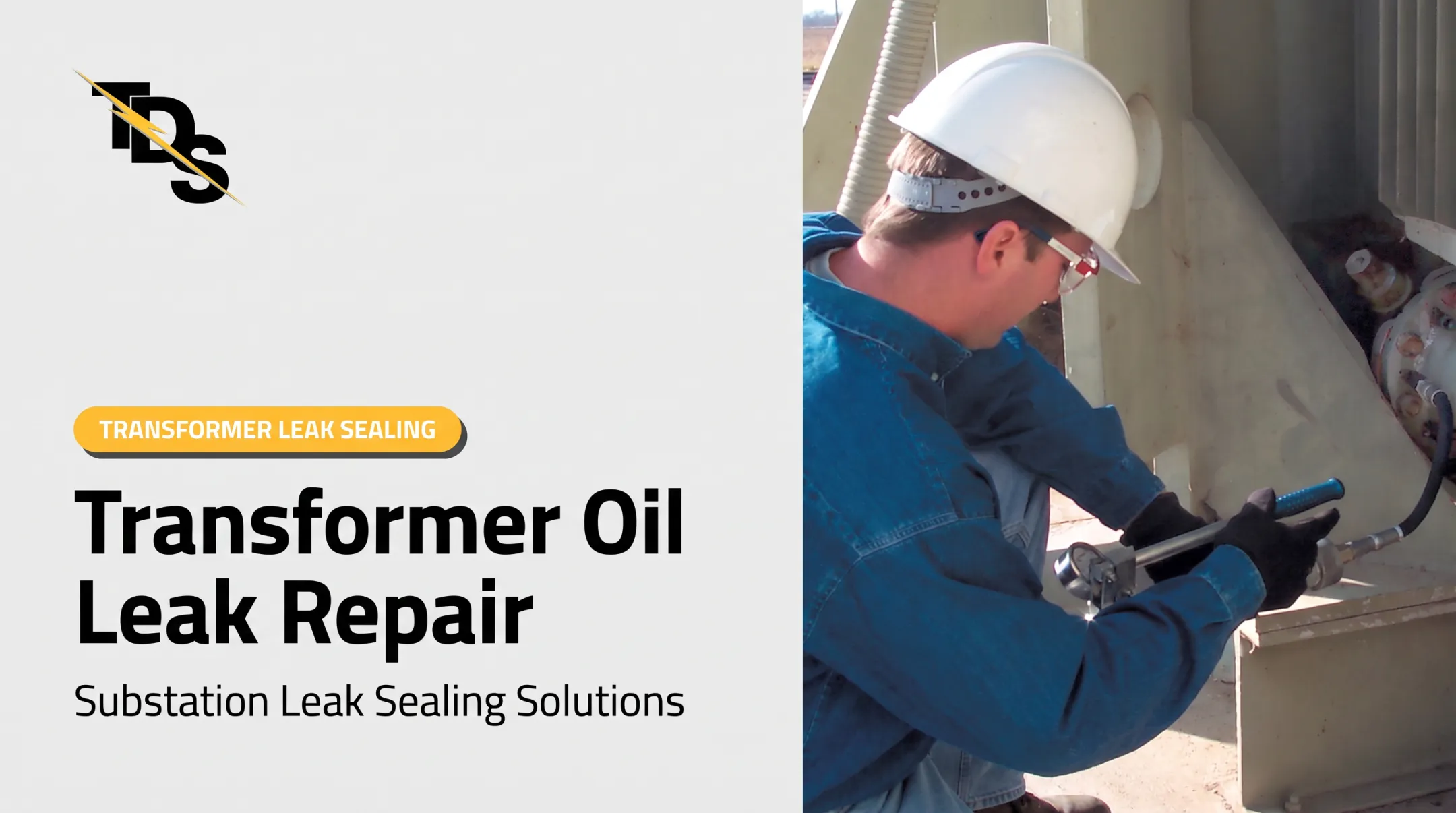
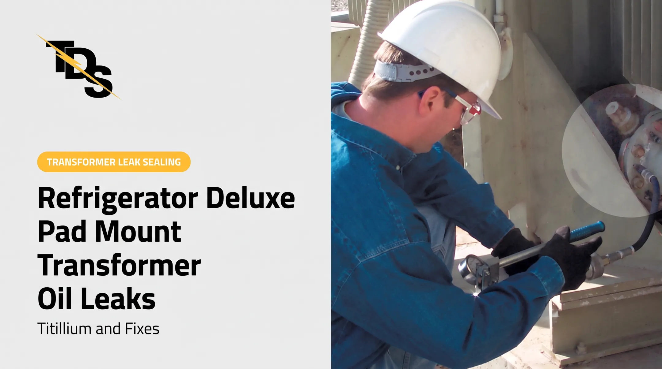
When disassembly or a long outage is undesirable, a specialist such as Transmission & Distribution Services (TDS) can survey the equipment and judge whether low-pressure leak sealing fits.
TDS describes its conventional drain-plug approach as plug removal, draining, and oil processing, versus sealing around the plug with an enclosure. For a 4-bolt flapper flange, TDS drills and taps four holes, injects sealant at low pressure, and plugs the holes after curing. Crews often finish that work in about two hours without draining oil.

Suitability still depends on leak location, equipment condition, safety requirements, and whether the repair can be verified. Ask for references and documented results rather than relying on vendor claims alone.
Step 4: Control and Protect the Transformer Oil
- Use clean, compatible collection and containment equipment.
- Protect oil from water, dirt, air ingress, and accidental release.
- Consider sampling, filtration, dehydration, level correction, or added testing if the leak ran a long time or the transformer was opened.
ASTM D923 covers representative sampling of insulating liquids. Follow the OEM for intervals and reconditioning.
Step 5: Test and Validate the Repair
- Inspect after repair and run the leak, pressure, vacuum, or operational checks specified by the OEM or engineering procedure.
- Confirm the valve operates correctly and the oil level is restored.
- Watch for new seepage across normal operating and temperature conditions.
No universal post-repair test pressure exists. Eaton's 5 psig figure is a factory routine test, not a field standard.
Step 6: Document and Monitor the Result
- Record the failure mode, parts and seal materials, oil handled, test results, photos, and follow-up needs.
- Set a monitoring interval based on criticality and repair method.
- Compare later inspections to the repaired area instead of relying on one visual check.
When Should You Repair vs Replace the Drain Valve?
The repair-or-replace decision balances leak severity, component condition, transformer criticality, contamination risk, outage constraints, parts availability, and long-term reliability. No public standard sets a replace-or-repair threshold, so rely on the OEM and qualified engineering judgment.

- Repair when the leak is limited to a replaceable gasket, packing, or connection, and the body, threads, seat, and tank interface are sound.
- Replace when the body or internal parts are cracked, severely corroded, distorted, damaged, wrongly rated, incompatible with the insulating fluid, or cannot isolate reliably after repair.
- Investigate the tank when oil comes from a weld, nozzle, seam, radiator connection, or a component above the valve.
- Get a specialist assessment when traditional removal would mean major outage, disassembly, oil-handling, or environmental problems. Low-pressure sealing methods may avoid full removal; confirm the method fits your equipment.
After either path, complete these checks before closing the issue:
- Leak testing and operational checks
- Oil-level verification and cleanup
- Documentation and follow-up inspection
Common Mistakes and Preventive Measures
Common Mistakes to Avoid
- Tightening fittings before confirming the source.
- Using incompatible gaskets or sealants.
- Forcing a seized handwheel.
- Opening the valve without containment.
- Ignoring oil contamination.
- Skipping post-repair testing.
- Working without required isolation and PPE.
Preventive Measures to Avoid Future Leaks
Inspect the valve, stem, flange, tank interface, and nearby fittings routinely. Look for corrosion, oil residue, damaged protective caps, and oil-level changes.
The Reclamation guide recommends in-depth inspection after the first month in service and annually after that, though intervals vary by owner.
Exercise and maintain valves only per OEM instructions. Keep accurate records of valve operation, oil sampling, leak history, repairs, parts, and findings.
Practical steps that reduce outage risk include:
- Use compatible materials
- Protect sealing surfaces from contamination
- Keep spill control ready before valve work
- Escalate recurring leaks rather than treating the same symptom repeatedly
Under 40 CFR 112, SPCC applicability starts at 1,320 gallons of aggregate aboveground oil capacity at qualifying facilities. These are facility-level rules, not automatic triggers for every valve leak.
Conclusion
A drain valve leak may be a simple seal or connection problem, or it may signal valve damage or a larger tank issue. Diagnose first, then repair.
Qualified workmanship, the right components, post-repair testing, and specialist support when you need it protect insulating oil, equipment reliability, environmental compliance, and uptime.
Frequently Asked Questions
What happens if a transformer leaks?
The unit loses oil that provides insulation and cooling, and moisture or contamination can enter. Leaks also create environmental and slip concerns. Qualified personnel should find and address the source promptly.
Can a transformer work without oil?
Oil-immersed transformers need their specified insulating and cooling liquid. Dry-type transformers are designed without oil. Never run an oil-filled unit below its required level.
What is a drain valve in a transformer?
A drain valve is the controlled outlet used to drain or sample insulating oil. Its seals and connections must prevent leakage during normal service.
What is an oil-immersed transformer?
An oil-immersed transformer uses insulating liquid around the core and windings for electrical insulation and heat transfer. The liquid's condition directly affects maintenance needs and reliability.