
Introduction
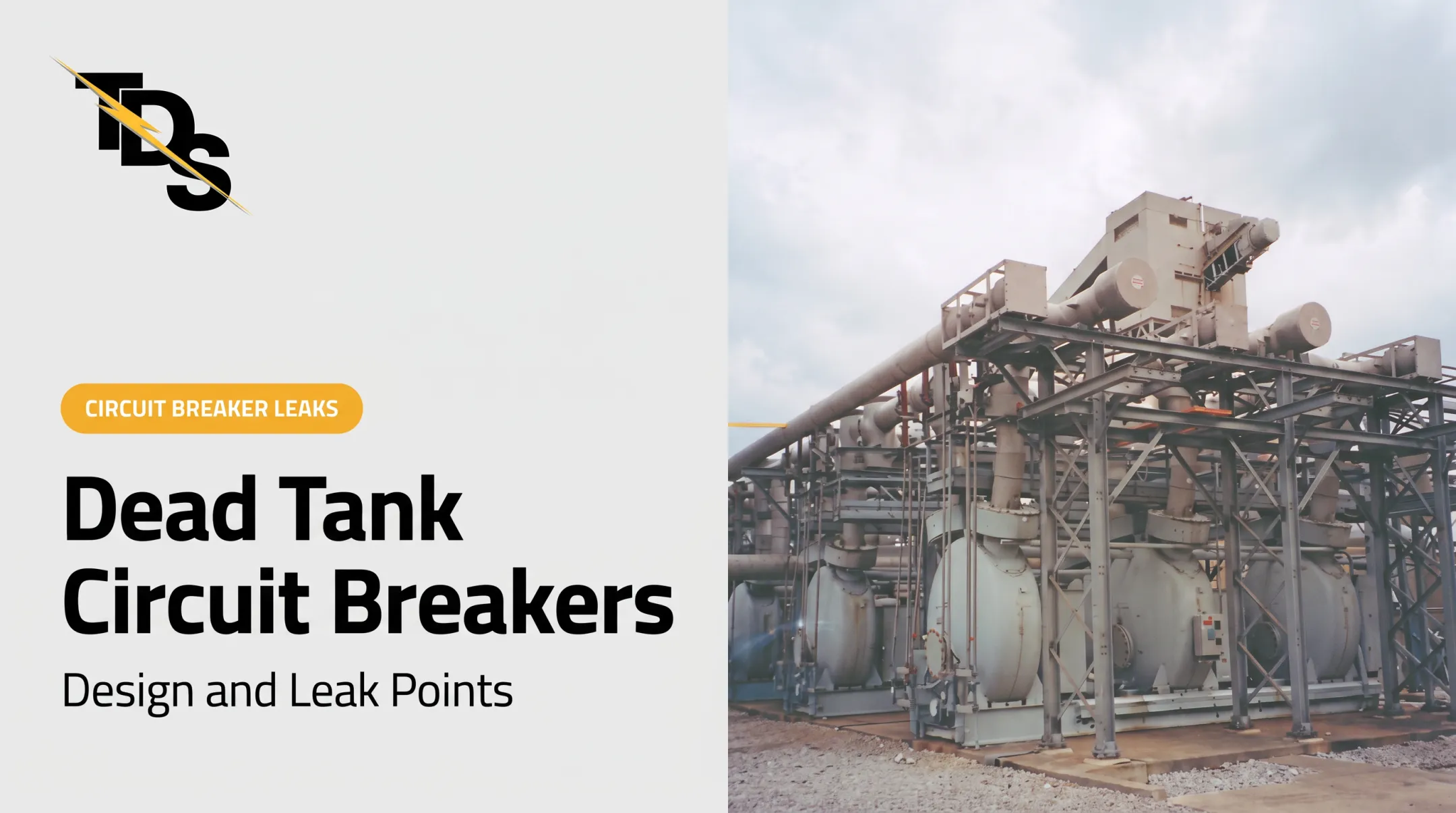
Utilities choose gas-insulated substations when land is tight, contamination is heavy, or reliability can't slip. The trade-off is a sealed gas envelope. Once that gas leaks, the compact design that made GIS attractive becomes a maintenance problem.
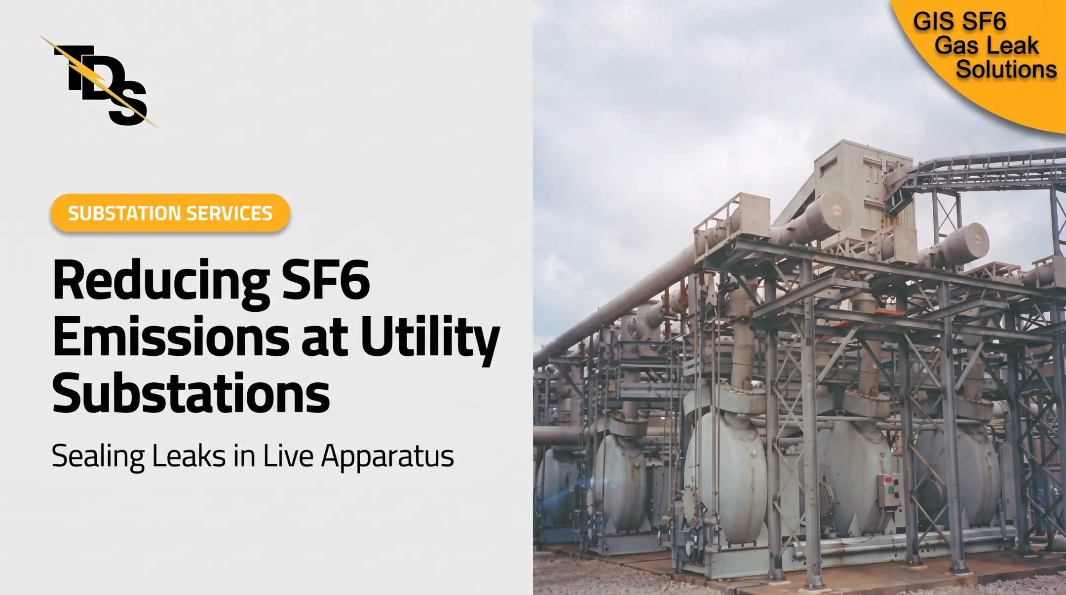
Most installed GIS still use SF6, and its climate impact is severe. IPCC AR5 lists a 100-year global warming potential of 23,500 and an atmospheric lifetime of 3,200 years.
This article covers GIS design, major components, common leak locations, the consequences of gas loss, and how to detect and repair leaks. Reliable GIS depends on sound initial design and a documented leak-management process that follows OEM, safety, and US regulatory requirements.
Key Takeaways
- GIS houses high-voltage parts inside grounded metal enclosures filled with insulating gas.
- Leaks cluster at flanges, seams, fittings, and monitoring connections.
- A falling density trend calls for confirmation and risk assessment, not venting.
- Repair choice depends on leak location, gas type, outage needs, and OEM guidance.
What Is a Gas-Insulated Substation and How Does It Work?
GIS is the switchgear, not the whole site. IEEE C37.122-2021 covers gas-insulated substations above 52 kV. Transformers, control buildings, and protection systems often sit outside the GIS enclosure and connect to it through cables, overhead lines, or air-insulated busbars.
Pressurized gas separates energized conductors from grounded enclosures. That shrinks the clearances air would demand, which is why GIS fits in a fraction of the space. Insulation and arc interruption are separate jobs, though in SF6 breakers the gas does both.
SF6 has been common since the 1950s because of its high dielectric strength and arc-quenching ability. Newer products use other gases:
- Siemens' 8VN1 Blue GIS uses clean air (80% nitrogen, 20% oxygen) with vacuum interrupters, up to 145 kV.
- GE Vernova's B105 g3 uses a CO2/O2 mixture with 5% fluoronitrile, up to 245 kV.
Always confirm gas type, filling pressure, and operating limits in the specific manufacturer's documentation.
GIS Design: Main Components and Design Decisions
What components are typically included in GIS?
A typical GIS bay includes:
- Busbars and circuit breakers
- Disconnectors and earthing switches
- Current and voltage transformers
- Surge arresters
- Cable or overhead-line terminations
- Gas compartments, monitoring devices, and grounded enclosures
Compartmentalization divides the equipment into separate gas zones, so a problem can be isolated and diagnosed without exposing the whole installation. Density monitors, gauges, and alarms watch each zone. Siemens documentation describes gas-loss alarms and breaker-control blocking, with a variant that permits tripping before blocking. Stages and values are product-specific.

Design choices that affect reliability and leak exposure
Key decisions include:
- Rated voltage and current
- Busbar arrangement
- Single-phase or three-phase enclosures
- Indoor or outdoor installation
- Seismic, pollution, and temperature requirements
- Available footprint
Interfaces matter too. Transformer, cable, and overhead-line connections, grounding systems, and building penetrations all add installation and maintenance requirements beyond the enclosure itself.
Design for maintainability and gas integrity
Specify access to flanges, gaskets, valves, monitoring points, and terminations early. Clear labeling, compartment isolation, and gas-handling provisions save hours later.
Verify scope and edition of each standard before citing it in a specification:
- IEEE C37.122-2021 for GIS above 52 kV
- IEEE C37.20.9-2025 for gas-insulated metal-enclosed switchgear from 1 kV to 52 kV
- IEEE C37.123-2023 as the specification guide for GIS at 52 kV and above
- IEEE C37.122.3-2024 for SF6 handling
- OSHA 29 CFR 1910.269 and NFPA 70E for worker safety
IEEE C37.122.1-2014 is Inactive-Reserved, so don't present it as current.
Where GIS Leaks Occur and Why They Matter
Common GIS leak locations
Common leak paths include the following; confirm each against the OEM manual for your equipment:
- Flange and gasket joints
- Weld seams and enclosure castings
- Bushings and cable terminations
- Valves and gas piping
- Density-monitor connections and relief devices
EPA lists flanges, fittings, seals, bushings, and castings as leak locations. TDS also identifies piping, flange connections, and seam welds as typical GIS trouble spots. Susceptibility varies with design, age, installation quality, and whether an interface is static, movable, or disturbed during maintenance.
Causes that can create or accelerate a leak
- Gaskets that reach end of life and lose compression
- Defective gasket material or poor installation workmanship
- Improper torque or contaminated sealing surfaces
- Thermal cycling, vibration, or seismic movement
- Corrosion, transport damage, or contact during maintenance
EPA also points to poor maintenance, construction defects, and worn gas-cart hoses. No single cause applies to every GIS model or compartment.
Operational, environmental, and safety consequences
EPA states SF6 must stay above minimum functional pressure or density for a breaker to keep its dielectric properties. Falling density can trigger alarms, block breaker operation, force outages, or restrict operating conditions.

Leaks also create environmental and regulatory exposure:
- GHGRP Subpart DD (40 CFR Part 98) covers electric transmission and distribution equipment, with a general threshold of 25,000 metric tons CO2e per year. Sealed-pressure equipment is excluded from the nameplate capacity used in that threshold calculation, not from reporting altogether.
- EPA requires annual reports by March 31, with records kept at least three years.
- California's CARB rule is state-specific. It caps the SF6 emission rate at 1% per year and phases out acquisition of new SF6 equipment on a schedule by voltage and rating. It is not a national ban.
EPA inspections also ask whether utilities document oil and SF6 leaks and maintain a repair action plan. SF6 risks differ from oil leaks in transformers, which carry spill and fire concerns instead.
Escalate when you see:
- Repeated low-density alarms
- Unexplained pressure decline
- Top-ups becoming more frequent
- Detector readings or residue at a joint
- Moisture or contamination
Alarm thresholds are model-specific.
GIS vs AIS: Benefits, Trade-Offs, and Selection Criteria
| Factor | GIS | AIS |
|---|---|---|
| Insulation | Pressurized gas in sealed enclosures | Ambient air |
| Footprint | Compact; Hitachi Energy claims up to 70% smaller for its design | Larger land requirement |
| Weather and contamination | Enclosed, less exposed | Exposed |
| Maintenance access | Through sealed interfaces; specialized training | Open and visible |
| Leak risk | Gas containment responsibility | No gas envelope |
The 70% figure is a vendor claim, not a universal ratio. Comparable US capital and lifecycle cost benchmarks are scarce, so build the comparison from project-specific quotes.
GIS tends to win on:
- Constrained urban or industrial sites
- High-pollution areas
- Indoor and underground installations
AIS or a hybrid may suit sites with ample land, tighter budgets, planned expansion, or limited gas-handling capability. Hitachi's PASS module, for example, combines a gas-insulated bay with air-insulated busbars.
GIS isn't automatically better. Weigh land, budget, outage strategy, local technical capability, and gas-management obligations.
Detecting, Repairing, and Preventing GIS Leaks
Leak detection and confirmation
A falling reading shows gas loss, not its source. EPRI's 2013 update notes that pressure drops, density alarms, and fill records don't locate the leak.
Practical process:
- Review alarm trends and fill records against baselines.
- Inspect visually and check instrument calibration.
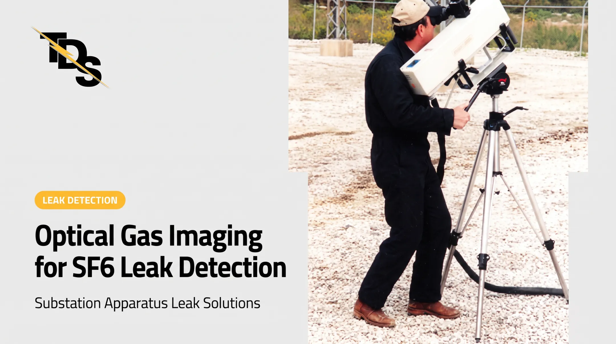
- Locate the source with soap solution, handheld or ultrasonic detectors, or SF6 infrared cameras.
- Confirm at the joint and note compartment boundaries.
Wind, noise, and survey thoroughness affect results. Infrared cameras depend on conditions such as no wind. TDS recommends infrared laser surveys with video records for quantification and exact location.

Risk assessment before repair
Weigh these factors before you commit to a repair method:
- Leak rate and compartment density
- Component criticality and equipment age
- Accessibility and proximity to energized parts
- Environmental obligations and OEM restrictions
- Outage consequences
OSHA 1910.269 requires that parts de-energized outside applicable procedures be treated as energized. Qualified personnel must control energized work, isolation, gas recovery, and disassembly under the site's electrical safety program. Don't vent SF6 voluntarily. It is about five times heavier than air and can displace oxygen in confined areas.
Repair and verification options
Conventional options include:
- Tightening or replacing hardware
- Replacing gaskets, seals, or damaged fittings
- Recovering and refilling gas
- Replacing a component
- Scheduling a planned outage
EPRI describes injected-sealant clamps and seam sealants for SF6 equipment, in some cases without draining or depressurizing. Its examples are case-specific, not blanket approvals.
Low-pressure sealing is one alternative where conditions allow. Transmission & Distribution Services (TDS), a Warrenville, Illinois, specialist working only in substations, applies a cured-in-place gasket or compatible rubber-based sealant instead of traditional teardown. Its process includes:
- Free equipment surveys listing the equipment, leak location, price, and method
- Low-pressure sealing for SF6 gas-filled GIS systems
- OSHA-certified technicians
- A four-year leak-seal warranty
TDS says many repairs can be made without degassing and sometimes while energized. Any outage may be limited to switching, grounding, and access. Suitability, energized work, and warranty coverage all require an equipment-specific evaluation.
Post-repair controls and prevention
After repair:
- Confirm the leak is stopped
- Watch pressure or density until it stabilizes
- Check gas quality where required
- Reset alarms and test function
- Document the component and schedule follow-up per the OEM
Then build a recurring integrity program:
- Trend monitoring
- Inspections after maintenance or abnormal events
- Torque and sealing controls
- Trained gas handlers
- Accurate records
- Clear escalation criteria for repeat leaks
EPA recommends inventory accounting, training, gas recovery, and leak detection and repair.
Frequently Asked Questions
How does a gas insulated substation work?
Metal-enclosed high-voltage components sit in pressurized insulating gas, which maintains electrical clearance. Breakers interrupt current and disconnect switches isolate circuits, while grounding switches ground them.
What is a gas insulated substation (GIS)?
GIS is gas-insulated, metal-enclosed switchgear used in a substation. The enclosure is distinct from the full site, which may include transformers and other systems.
Which is better, GIS or AIS?
Neither wins universally. The choice depends on footprint, site conditions, lifecycle cost, maintenance capability, and gas-management requirements.
What are the different types of gas insulated substations?
Classifications include indoor, outdoor, hybrid, single-phase or three-phase encapsulation, voltage class, and gas technology. Configurations vary by manufacturer.
What is 33kV GIS?
33 kV is the nominal voltage class. It falls under IEEE C37.20.9-2025's 1–52 kV scope. Confirm ratings, fault rating, and configuration from project specifications.
What is the purpose of GIS switchgear?
It switches, protects, isolates, grounds, measures, and distributes circuits inside a compact gas-insulated enclosure.