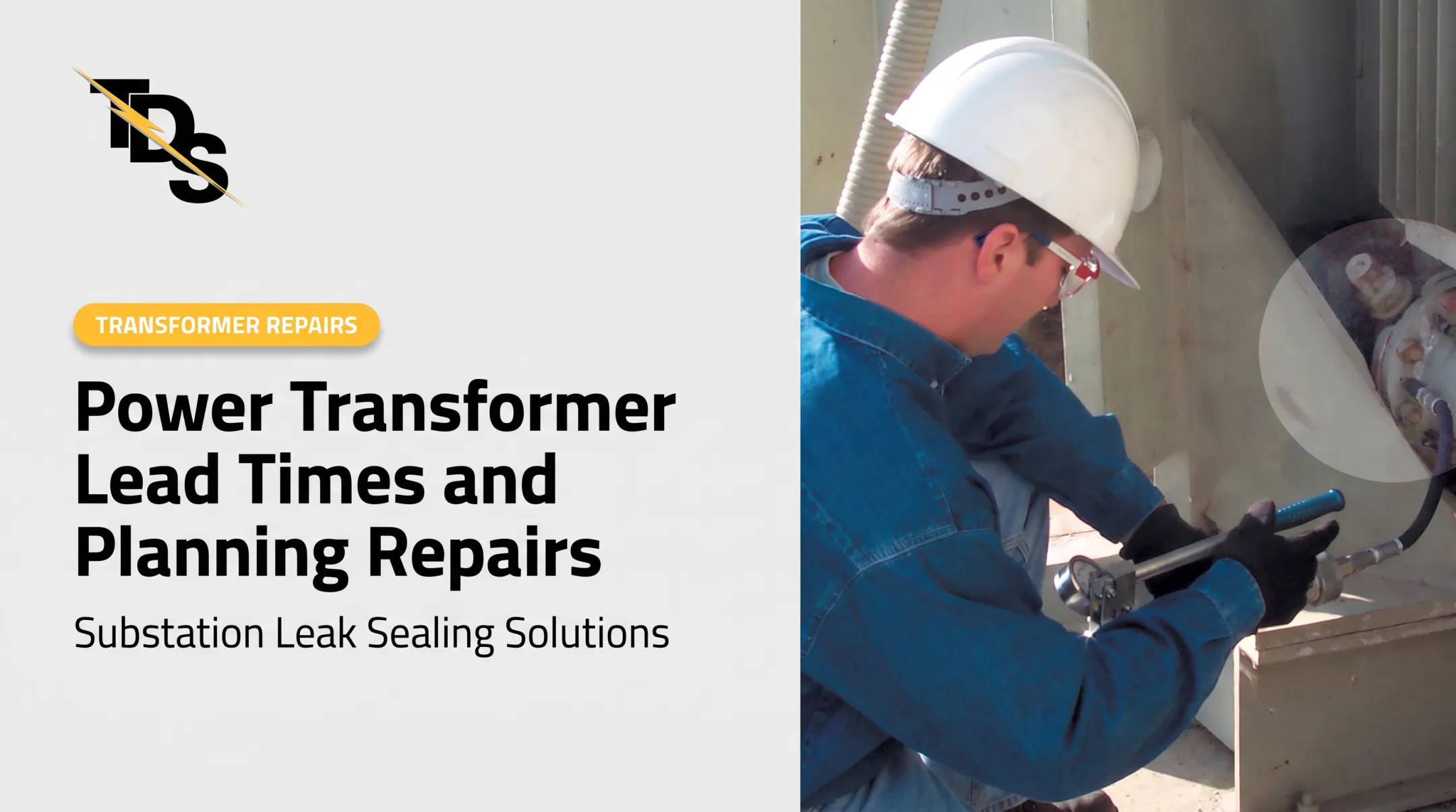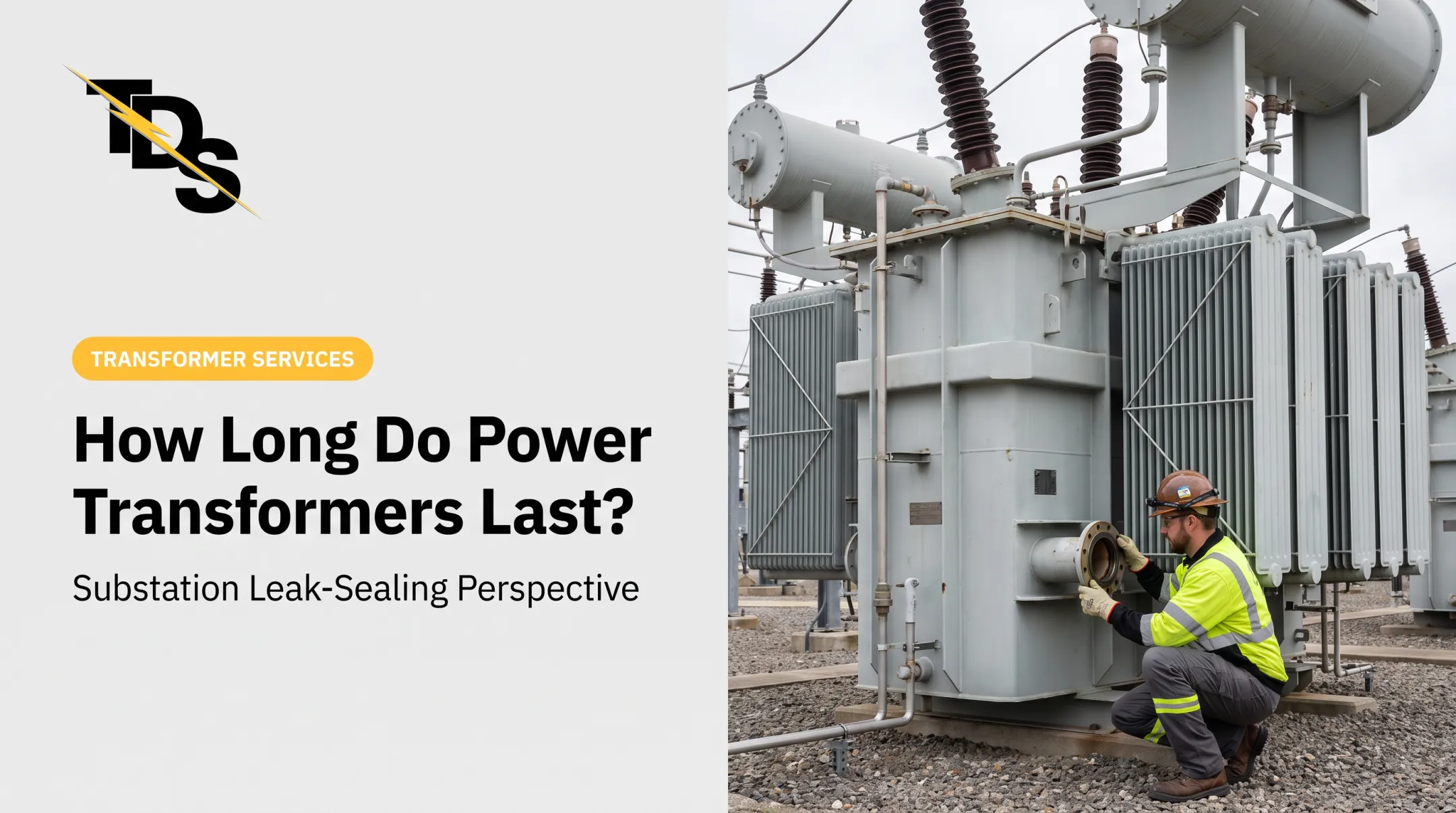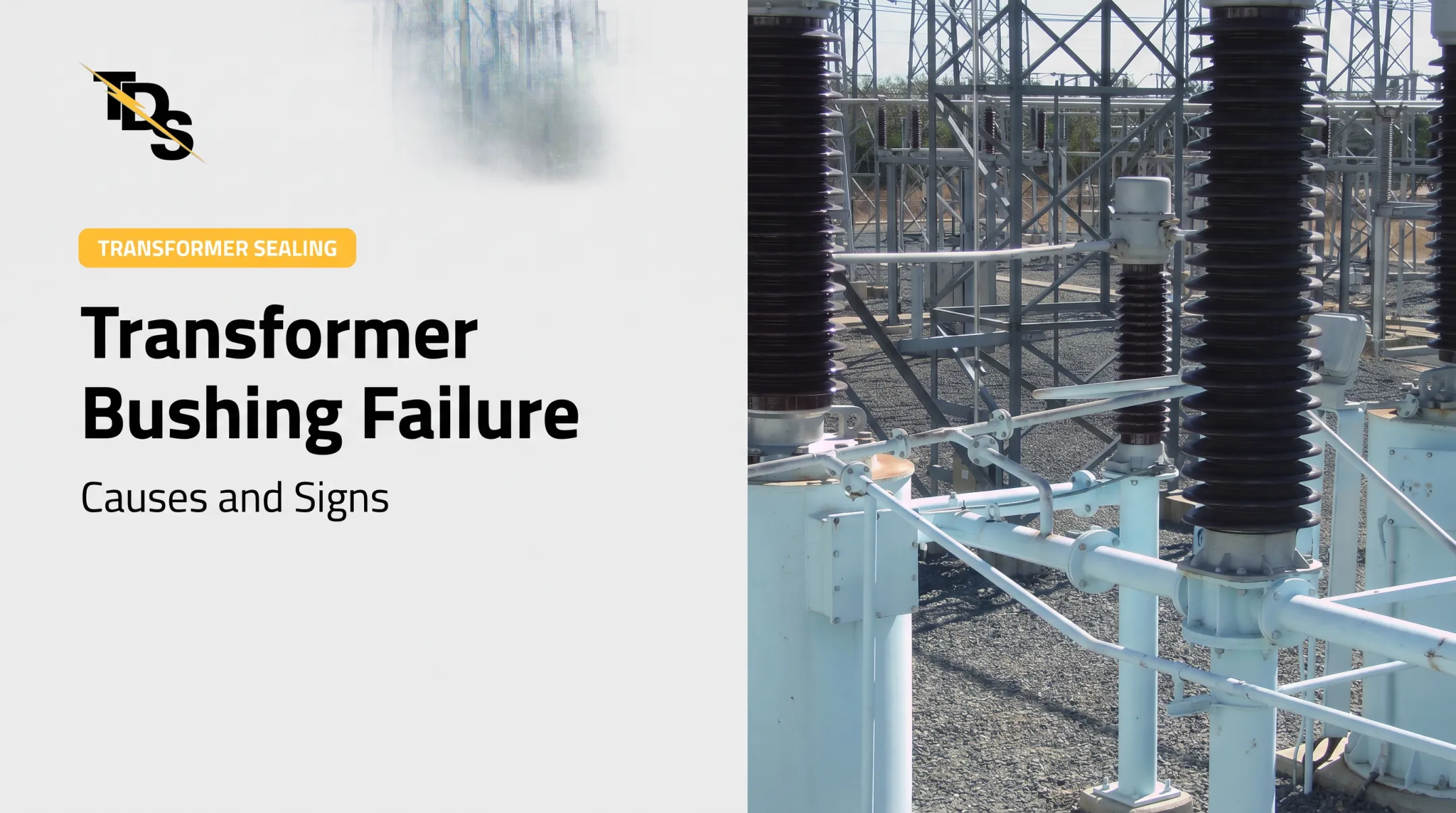

Replacement is slow. DOE's 2024 resilience report puts typical large-power-transformer lead times at about 36 months, with some reaching 60.
Understanding the root cause, rather than reacting to the final symptom, helps maintenance teams spot developing problems, plan repairs, and protect personnel. Only qualified personnel should assess energized high-voltage equipment, following site safety procedures.
Key Takeaways
- Heat, insulation aging, moisture, oil problems, electrical faults, mechanical damage, and poor application cause most failures.
- Investigate persistent overheating, odd sounds, oil leaks, dark oil, hot connections, and alarms promptly.
- Correct specification, loading, cooling, oil care, and protection prevent many avoidable failures.
- Qualified technicians decide whether a leak needs sealing, repair, refurbishment, or replacement.
Common Causes of Power Transformer Failure
Power transformer failure is the loss of a transformer's ability to safely convert voltage and maintain insulation. EPRI separates forced-outage failures, which need immediate removal from service, from scheduled-outage failures handled at a chosen time. High dissolved gas levels are one common trigger for a scheduled outage.
Developing defects such as a leak, hot spot, or degrading oil typically precede both types of outage.
Thermal Stress, Overloading, and Cooling Problems
Heat is the main accelerator of insulation aging. EPRI's aging work models life as a function of winding hot-spot temperature.
Common heat sources include:
- Loads above nameplate rating, such as a generator step-up unit running past design
- Unbalanced phases and high ambient temperatures
- Blocked radiators, failed fans, or restricted ventilation
- Harmonic currents from nonlinear industrial loads like drives and rectifiers
IEEE C57.91-2025 covers loading of mineral-oil-immersed transformers, and IEEE C57.110-2018 addresses capability under nonsinusoidal currents. Use those and the manufacturer's limits, not a generic temperature.
Moisture Ingress, Oil Loss, Contamination, and Insulation Aging
Leaking gaskets, seals, bushing flanges, valves, and fittings let oil out and moisture in. Less oil means weaker cooling and dielectric strength. Oxidized oil and aged cellulose then raise the risk of overheating, partial discharge, and arcing.
Typical external leak points include:
- Pipe-flange gaskets, bushing flanges, drain valves, and radiator valves
- Deteriorated 8-bolt butterfly-valve gaskets on larger units
- Failed stem packing on flapper and butterfly valves
Gaskets also fail from end-of-life degradation, defective material, or poor installation.
Electrical Stress and Power-Quality Disturbances
Lightning, switching surges, over-excitation, short-circuit forces, and repeated fault currents damage windings, bushings, tap changers, and insulation. CIGRE's 2015 survey attributes 31% of reported substation-transformer failure locations to tap changers. That is a share of failure locations, not an annual failure probability.

For thresholds and relay coordination, use IEEE C57.109-2018 (short-circuit withstand) and IEEE C37.91-2021 (transformer protection), plus your utility's own standards.
Mechanical Damage, Installation Errors, and Design or Manufacturing Defects
Hidden defects often start before energization or after an event:
- Transport impacts and vibration (see IEEE C57.150-2023)
- Earthquake loading and winding displacement
- Loose connections, poor workmanship, or incorrect grounding
- Specifications that don't match site requirements
Commissioning checks and post-event inspections catch many of these. Acceptance testing under NETA ATS before first energization sets the baseline. No reliable cause-by-cause failure percentages exist for these categories, so treat any you see quoted with caution.
What Happens If Power Transformer Failure Is Ignored
A minor leak, hot connection, or cooling fault can progress to insulation damage, internal arcing, winding failure, fire, or an oil release.
Downstream costs include:
- Forced outages
- Emergency work
- Damage to connected equipment
Severity depends on design, fault type, protection, and operating conditions.
Regulatory exposure matters too. EPA's SPCC rules under 40 CFR Part 112 can apply to facilities where oil could reach navigable waters, and oil-filled operating equipment is relevant to planning. Applicability depends on the facility, so not every transformer triggers a plan on its own. Unchecked leaks can also leave utilities exposed during EPA inspections.
Replacement is expensive. DOE's 2014 study gave 2010 estimates of $2 million to $7.5 million for 75-500 MVA units, plus 25%-30% for transport and installation. Those are dated figures, not current quotes.
Warning Signs You're About to Experience Power Transformer Failure
Warning signs call for qualified investigation. They don't prove a single root cause. Compare readings against the nameplate, commissioning data, manufacturer guidance, and the unit's own baseline.
Persistent Overheating, Localized Hot Spots, or Unusual Temperature Trends
Watch for:
- High oil or winding temperatures
- Uneven phase temperatures
- Hot bushings or terminations on thermal scans
- Cold radiator sections or failed fans and pumps
These may point to overload, poor circulation, loose connections, imbalance, or internal problems. Reclamation's FIST 4-1B schedules annual infrared inspection of the transformer, bushings, and wiring.
Oil Leaks, Low Fluid Levels, Discolored Oil, or Pressure and Level Alarms
Seepage, unexplained level drops, sludge, darkened oil, and alarm activity all warrant prompt evaluation. Sludge also hurts cooling.
Transmission & Distribution Services (TDS) specializes in low-pressure leak sealing for substation apparatus. Its technicians clean suspect flanges and apply an oil leak detector, which darkens at the flange split line when a gasket is leaking.
TDS then repairs only the leaking component with a cured-in-place gasket, often avoiding traditional disassembly. Free surveys document the equipment, leak location, repair method, and price.

Not every leak can be repaired while energized. Site conditions decide.
Unusual Humming, Buzzing, Popping, Burning Odors, Relay Trips, or Visible Component Damage
A steady hum is normal. Core magnetostriction produces it at twice line frequency, 120 Hz on a 60 Hz system. A sudden change in tone or volume is the red flag.
Isolate the equipment per your emergency procedures and call qualified support if you see:
- Smoke or burning odors
- Repeated relay operations
- Cracked or contaminated bushings
- Corrosion, tank deformation, or signs of arcing
How to Prevent Power Transformer Failure
Prevention combines correct engineering, controlled operation, condition monitoring, timely repair, and documented safety practice. No single test does it.
Specify, Install, and Commission the Transformer for the Actual Application
Specify against the real application:
- Load profile and future demand
- kVA, primary and secondary voltage, frequency, phase configuration
- Harmonic content and cooling class
- Insulation, enclosure, ambient conditions, elevation, and grounding
At commissioning, verify the nameplate, inspect connections, check protection, and run applicable electrical tests. IEEE C57.93 guides installation.
Control Loading, Cooling, and Power Quality
Balance loads, keep ventilation clear and radiators clean, and confirm fans and pumps work. Check tap settings, assess harmonics, and coordinate surge protection and relays. Trend temperatures and power-quality readings. One-time observations mislead.
Protect Oil, Seals, Bushings, and Insulation
Routine checks should cover oil level, oil sampling, moisture, dissolved gas analysis (IEEE C57.104-2019 guides interpretation), bushing condition, corrosion, and seals. Fix external leaks early to prevent oil loss, moisture ingress, and secondary insulation damage.
On cooling systems, 6- and 8-inch dresser couplings may need gasket replacement when extra tightening doesn't stop a leak.
Use Condition-Based Maintenance and Inspect After Abnormal Events
Base the plan on transformer type, age, criticality, environment, and history. Reclamation's FIST 4-1B (May 2024) offers example intervals, adjustable for condition:
| Activity | Example interval |
|---|---|
| Oil temperature, pressure, level, leak checks | After one month, then annually |
| Cooling fans, controls, pumps | After one month, then annually |
| Dissolved gas analysis | Annually |
| Infrared inspection | Annually |
| Winding power factor and excitation | Before energizing, then every six years |

Add SFRA (IEEE C57.149-2024), ratio testing, and relay-event review. Inspect after storms, faults, transport, or seismic events, using qualified personnel.
Tips for Long-Term Prevention and Control
Build a baseline and trend it. Isolated readings aren't definitive. Combine visual checks, gauge readings, thermal scans, oil reviews, and alarm history.
- Set intervals from manufacturer guidance, criticality, age, loading, and environment.
- Log readings, test reports, repairs, leaks, relay operations, and weather events in one asset history.
- Add online monitors or thermal tools only where they produce actionable trends. NYPA ordered nearly 50 additional DGA monitors for critical transformers.
Train operators and contractors. Crews should recognize abnormal sounds, odors, hot spots, oil loss, and alarms, and know when to escalate to an engineer or specialist.
Follow approved procedures for switching, lockout/tagout, sampling, and emergency isolation. OSHA 1910.269 covers power generation, transmission, and distribution work.
Use leak surveys for planning. Some leaks get sealed now; others are contained until a planned overhaul or replacement.
Conclusion
Transformer failure usually has identifiable contributors:
- Heat
- Moisture
- Insulation deterioration
- Electrical stress
- Mechanical damage
- Poor installation
- Age
Proactive monitoring, correct operation, timely leak and component repair, and qualified diagnostics reduce disruption and improve reliability. Not every warning sign calls for replacement.
Frequently Asked Questions
How long does it take to fix a transformer failure?
It depends on the fault, unit size, damage, access, outage windows, parts, and whether you repair, refurbish, or replace. DOE cites about 36 months as a typical large-unit replacement lead time, but no universal repair timeline exists.
What are the signs that a transformer is failing?
Look for persistent overheating, abnormal sounds or odors, oil leaks or discoloration, unusual alarms, hot connections, visible damage, and abnormal test results.
What causes transformer failure?
Common causes include thermal stress, overload, cooling problems, moisture, oil deterioration, insulation aging, surges, mechanical damage, specification or installation errors, manufacturing defects, and neglected maintenance.
What happens when a transformer fails?
The unit may trip offline or lose voltage-conversion capability. That can mean outages, equipment damage, fire or oil release, and an urgent repair-or-replace decision.
What is the average lifespan of a transformer?
DOE describes about 40 years as typical design life, with some units running beyond 70. Actual life depends on loading, climate, maintenance, and insulation condition.
How can I reduce transformer losses?
You can reduce losses, not eliminate them, through correct sizing, balanced loading, sound connections, adequate cooling, harmonic control, and routine monitoring.