
Introduction
Every oil-filled transformer is a heat problem waiting to happen. Core losses and winding losses never stop, and the oil carries that heat out of the tank. Radiators and cooling fins give it somewhere to go.
Per DOE definitions, no-load loss comes from excitation, while load loss includes winding and stray losses. If the radiator can't shed that heat, insulation suffers.
This guide is for utility and substation personnel. It covers radiator components, natural and forced cooling, radiator types, and inspection and maintenance for liquid-filled transformers.
Key Takeaways
- A radiator is a heat exchanger moving heat from insulating oil to ambient air.
- Fins, panels, and tubes add surface area; they are one part of the cooling system.
- Airflow, oil circulation, cleanliness, valves, fans, and pumps all affect performance.
- Repairs and cooling changes need OEM instructions and qualified safety procedures.
What Is a Transformer Radiator and How Does It Work?
Why Transformers Need Cooling
Core and winding losses raise oil, winding, and top-oil temperatures. Excess heat accelerates insulation aging and oil deterioration. IEEE C57.91 addresses temperature criteria, cooling, and the insulation damage that above-nameplate loading can cause. Use the current edition for numeric limits rather than older published figures.
What the Radiator Is (and Isn't)
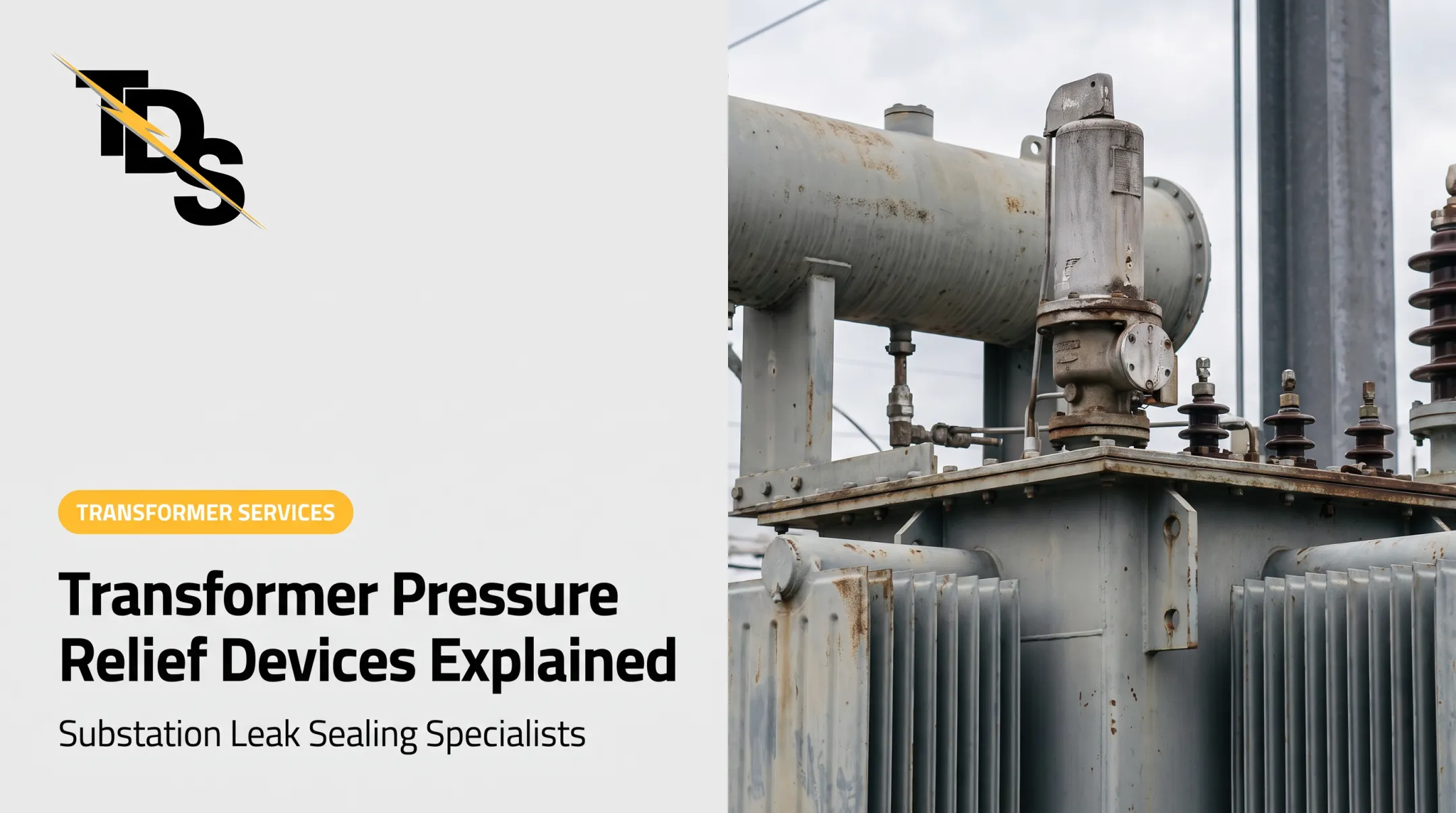
A radiator is an external or integrated heat-transfer assembly used mainly on liquid-filled transformers. It is a distinct assembly from the main tank. Oil flows through it, and it works with headers, valves, fans, pumps, and temperature sensors rather than replacing them.
The ONAN Cycle
- Oil heated by the core and windings rises in the tank.
- It enters the radiator through the upper connection.
- It travels down the panels or tubes, releasing heat through the metal to the air.
- Cooler, denser oil returns through the lower connection.

Natural convection drives this loop. Fans improve the air side, and pumps force oil circulation in designs built for it.
Radiators and Ratings
A radiator helps the transformer meet its designed thermal performance. It does not raise the nameplate rating on its own.
Approved loading depends on the full cooling designation, controls, auxiliary equipment, and the manufacturer's rating. One project schedule, for example, lists 84/112/140 MVA across three cooling stages, which shows how ratings track each cooling stage.
What Are Cooling Fins and What Types of Radiators Are Used?
Fins and Radiator Constructions
Cooling fins are extended metal surfaces, channels, or folded sections that increase heat-transfer area. The term means different things on pressed-panel, corrugated, and tubular designs.
Common constructions:
- Plate or panel: one manufacturer describes 19-gauge plates with integrated headers, in stainless or galvanized material.
- Corrugated tank wall: an integral design whose elastic walls also absorb oil-volume changes in sealed units.
- Tubular: oval steel tubes welded to caps, with welded collectors and flanged connections.
No single type clearly ranks better for heat transfer, service life, or corrosion resistance. Compare compactness, airflow, durability, and serviceability for your unit.
Integrated vs. Detachable Radiators
Corrugated walls and integrated radiators are part of the tank. Detachable banks connect through upper and lower headers, flanges, gaskets, and isolation valves.
The Bureau of Reclamation guide notes that valved sections can be removed for cleaning or leak repair without draining the tank. Direct-attached sections have no valves. Valves also support transport, installation, and local isolation, but procedures depend on the design and oil-handling requirements.
Selection Factors
- Transformer losses and required cooling class
- Available space, ambient temperature, and airflow
- Corrosion exposure and coating system
- Mechanical loading
- Access for cleaning or replacement
Many larger transformers use 8-bolt butterfly valves between radiator and main tank. Their flange gaskets are a frequent leak point, so consider access to them early.
How Do Transformer Cooling Classes and Radiator Design Choices Compare?
Cooling Classes at a Glance
| Class | Oil | Air/Water | Role of equipment |
|---|---|---|---|
| ONAN | Natural | Air natural | Radiators only |
| ONAF | Natural | Air forced | Fans on radiators |
| OFAF | Forced | Air forced | Pumps plus fans |
| OFWF | Forced | Water forced | Oil-to-water heat exchanger |
Capacity gains from stepping up a class vary by design. One 2024 overview cites a 2,500/3,125 kVA unit, a 25% rise from ONAN to ONAF. That figure is an illustration, not a standard increment.
How Engineers Choose
Selection depends on several site and design factors:
- Thermal design and load profile
- Ambient range and site ventilation
- Noise limits and auxiliary power
- Reliability needs and cooling-failure consequences
A project specification may also record ambient temperatures, a sound limit, staged ratings, and radiator count.
Layout and Hydraulics
Connection location, header sizing, and oil-flow distribution matter. Trapped air or blocked passages can cause uneven cooling and hot spots. An IEEE seminar advises checking oil velocity and duct flow in pumped, non-directed designs to avoid winding hot spots.

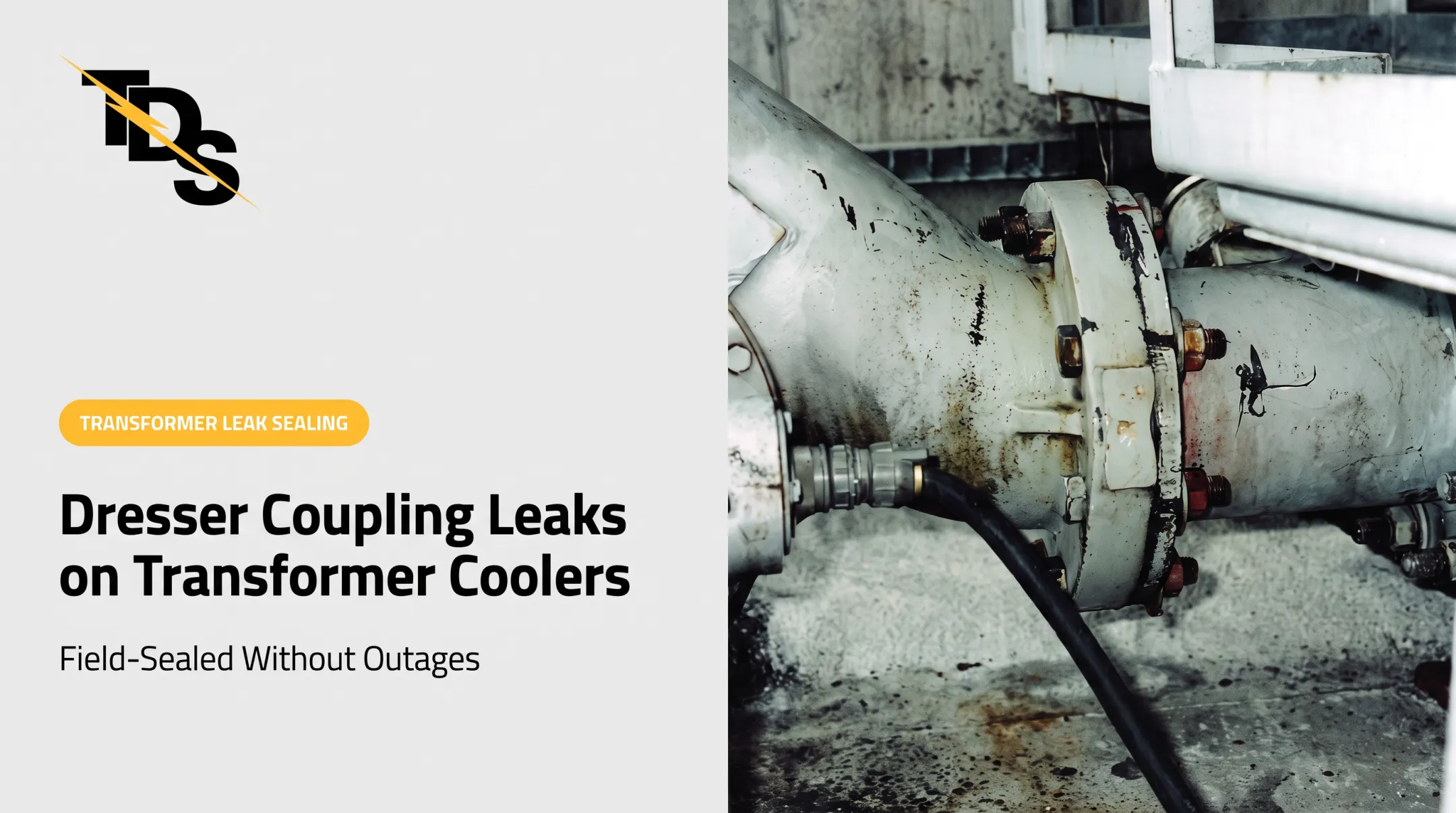
Many large units also have 6- and 8-inch Dresser couplings in the cooling system, another point to watch for seepage.
Adding Fans, Pumps, or Radiators
Don't bolt on cooling to an existing unit casually. Retrofits need engineering review, control integration, protection checks, and confirmed manufacturer-approved ratings. Manufacturer manuals describe fan options and temperature-based control, but none supply a universal retrofit factor.
Specification Checklist
- Nameplate and cooling designation
- Radiator dimensions
- Connection and valve arrangement
- Fin or panel construction
- Material and corrosion protection
- Fan or pump requirements
- Sensor and control details
- Applicable standards (such as IEEE C57.12.00 and C57.12.10)
- Required documentation
How Should Radiators and Cooling Fins Be Inspected and Maintained?
Visual Checks
Follow the OEM's interval and your site safety program, not a universal schedule. Look for:
- Oil seepage at flanges and valves
- Corrosion, coating failure, and dented or distorted fins
- Unusual oil levels
- Blocked airflow
- Signs of overheating
Condition-Based Checks
Industry guidance points to compressed-air cleaning for dirty finned radiators and infrared inspections for hot spots. The EPRI monitoring guide flags blocked radiators as a cause of poor heat exchange, along with fan, pump, and control failures.

Useful checks:
- Approved radiator cleaning
- Fan and pump operation tests
- Valve and control verification
- Oil-flow assessment
- Infrared scans for uneven temperature patterns
Evaluating Leaks
Evaluate leaks promptly. Oil loss can affect cooling, insulation, environmental compliance, and availability. Under 40 CFR Part 112, SPCC applicability is set at the facility level, so check with your compliance group.
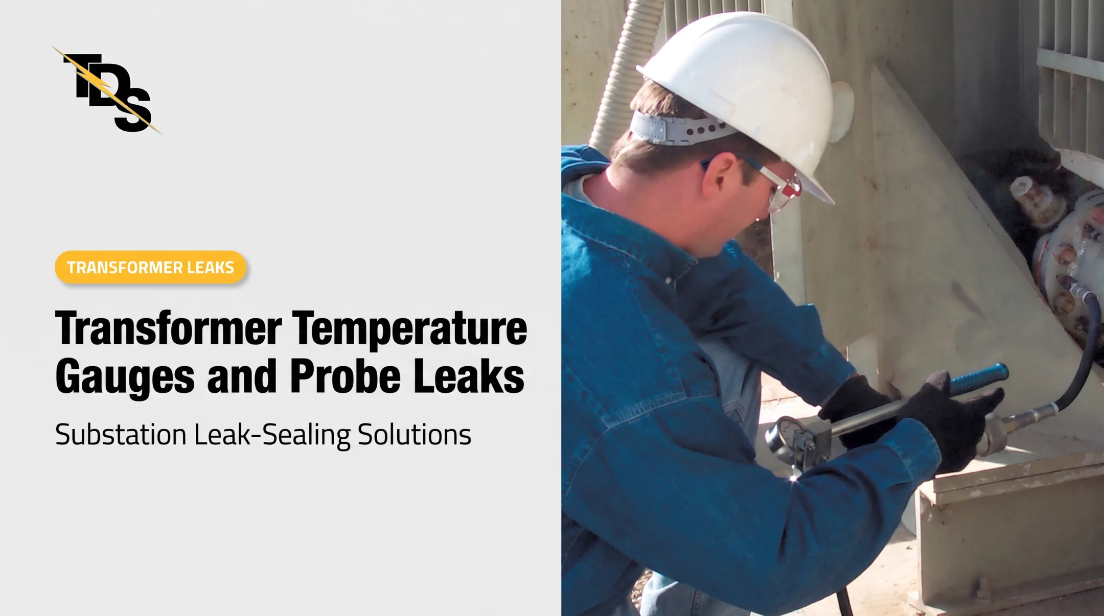
Conventional repair means de-energizing, grounding, and draining the radiators, often the main tank too. Transmission & Distribution Services (TDS) offers low-pressure leak sealing for oil-filled substation apparatus. Its work covers radiator fins, flange gaskets, drain valves, and valve-stem packing.
Some examples from TDS procedures:
- An 8-bolt flange can usually be repaired in about three hours.
- A 4-bolt flapper-valve flange usually takes about two hours, without draining oil.
- Bottom connections can be done energized; upper leaks may need de-energizing and grounding, depending on proximity to bushings.
TDS surveys are free and identify the equipment, leak location, repair price, and method. Not every radiator or valve leak is repairable in service, and the survey is where that gets decided.
Conclusion: Keeping Transformer Cooling Reliable
Radiator performance depends on the whole system: heat-transfer surface, oil circulation, airflow, valves, fans or pumps, controls, and environment. A clean radiator can't compensate for a dead fan or a closed valve.
Use manufacturer-approved procedures and qualified substation personnel for inspections, cooling changes, leak repairs, and decisions on continued operation. Before any repair, TDS meets with customer engineering and maintenance staff to review procedures and warranty follow-up. That coordination is a good model for any contractor.
Frequently Asked Questions
What is a radiator in a transformer?
It is a heat-transfer component that carries warm insulating oil and releases the heat to ambient air through panels, fins, or tubes.
How is a transformer cooled?
Depending on its cooling class, it uses natural oil and air circulation, fan-assisted airflow, forced oil circulation, or oil-to-water heat exchangers.
What is the purpose of radiator fins?
Fins increase exposed surface area so heat moves from the oil, through the radiator metal, into the surrounding air.
What is the price of a transformer radiator?
Price varies with transformer rating, dimensions, construction, materials, coatings, valves, fans, shipping, and installation. Gather specifications before requesting a quote.
What is the difference between a transformer radiator and cooling fins?
The radiator is the complete heat-exchange assembly. Fins are the extended surfaces or channels that help it release heat.
Can transformer radiator leaks be repaired without removing the radiator?
Some can, when the leak location, equipment condition, safety controls, and repair method allow. Others require isolation, oil handling, replacement, or a manufacturer-approved outage.