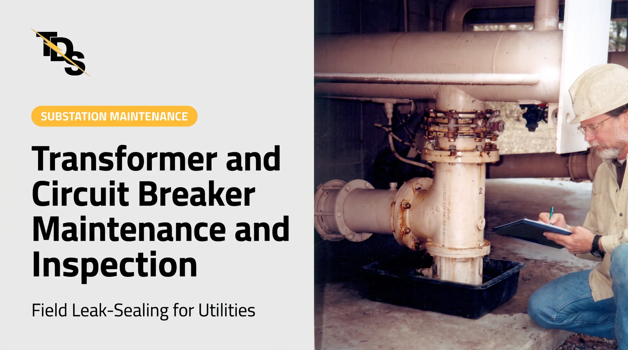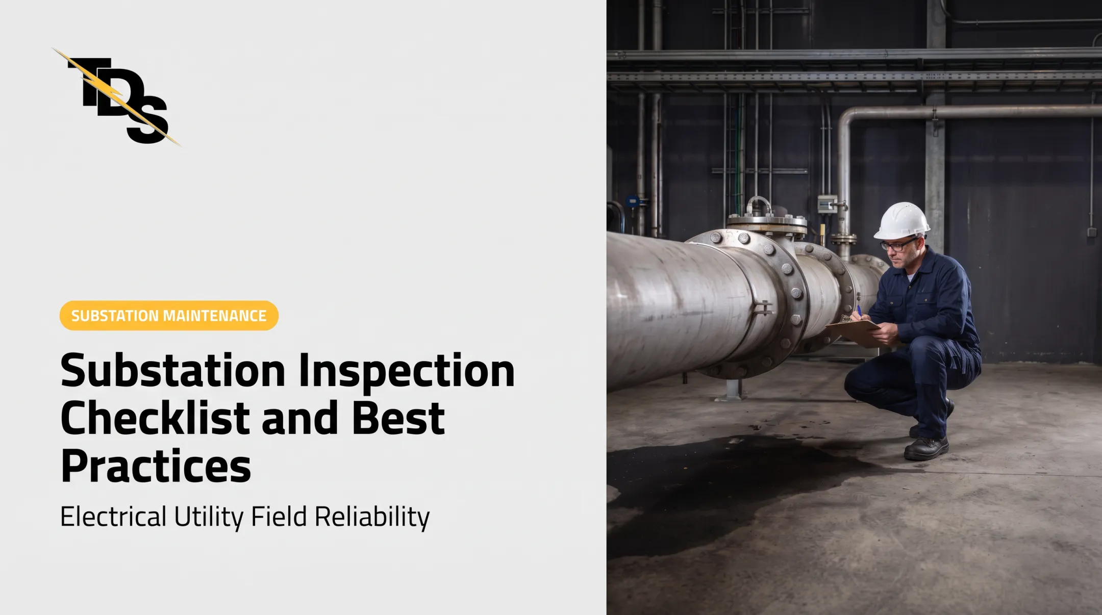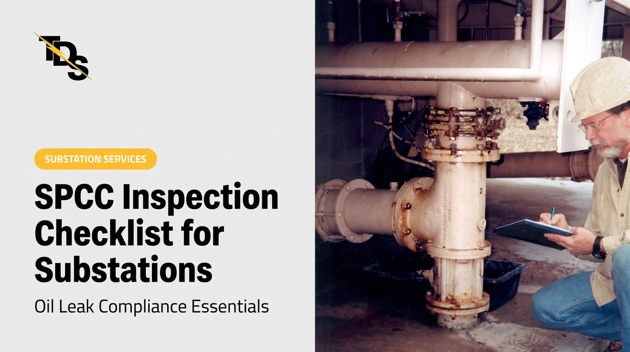

A CIGRE survey of 964 major transformer failures across 58 utilities found that windings, tap changers, and bushings were major contributors. Many of those subsystems show external symptoms first.
This checklist covers preparation, visual and operating checks, targeted diagnostics, interpretation, documentation, and escalation. Energized work and specialized testing must follow your utility's procedures and be performed by qualified personnel.
Key Takeaways
- Inspect the tank, bushings, connections, cooling gear, gauges, alarms, and oil containment on every visit.
- Add infrared, oil analysis, or electrical testing when criticality, history, or findings justify it.
- Judge readings against OEM limits, baselines, load, ambient conditions, and trends, never one data point.
- Record time-stamped readings, photos, defect locations, severity, and assigned actions.
- Stop and escalate for active leaks, abnormal temperatures, alarms, or any unsafe condition.
What You Need to Check a Transformer in a Utility Substation
Start with the right asset data, safe access, and suitable tools. Adapt the checklist to transformer type, voltage class, oil or dry construction, accessories, OEM instructions, and your maintenance program.
Tools and Indicators Required
Bring the basics:
- Approved checklist, nameplate data, and asset drawings
- Flashlight, camera, binoculars, and radio
- PPE suited to the job briefing
- Calibrated thermometer or thermal imager, plus instruments used by qualified personnel
Then locate the installed indicators: oil-level gauge, pressure/vacuum gauge, oil and winding temperature indicators, annunciator status, fan and pump status, tap-changer position, bushings, and containment.
Know which instruments need calibration and which readings are only indicative. Bureau of Reclamation guidance calls for thermometer testing every 3-5 years and whenever trouble is suspected, though that is not a universal interval for every gauge model. Some tests also require a de-energized state, laboratory analysis, or engineering review.
Preconditions and Setup
Before entering the yard, review:
- Switching plan and one-line diagram
- Prior inspection records and open work orders
- Recent loading and alarm history
- Weather and known hazards
Follow your utility's access, approach-boundary, grounding, lockout/tagout, arc-flash, and environmental rules. For US utilities, OSHA 1910.269 governs transformation equipment work. It requires job briefings, limits exposed energized work to qualified employees, and requires an estimate of arc incident energy. Note that 1910.147 excludes installations under exclusive utility control, so check which rule applies to your site.
Record load, ambient conditions, oil or winding temperature, tap position, cooling stage, and time. Without that context, later readings can't be compared accurately.

Methods to Check a Transformer in a Utility Substation
No single method gives a complete condition assessment. Begin non-intrusively, then add thermal, oil, or electrical diagnostics based on criticality, history, abnormal indications, and your approved maintenance plan.
Method 1: Visual Inspection and Leak Survey
What to cover: tank, conservator, radiators, valves, welds, gaskets, covers, bushings, cable boxes, tap-changer components, arresters, grounding, supports, paint, corrosion, containment, and signs of water or pest ingress.
Tools: checklist, asset photos, lighting, binoculars, camera, and an approved way to confirm suspected oil residue without disturbing energized equipment.
- Confirm the asset ID, start at a safe observation point, and walk the same route every time.
- Record active drips, wet or fresh oil, staining, cracked seals, loose hardware, rust-through, paint failure, damaged bushings, blocked radiators, and fan or pump defects.
- Photograph each finding, tie it to a specific component, note whether it looks active or historical, and compare with prior records before setting priority.
Bureau of Reclamation guidance lists gaskets, flanges, bushings, valves, radiators, welds, and tanks as typical leak points. For bushings, look for cracks and carbon tracking, and inspect more often where salt or dust accumulates.
One caution: a flange that looks wet isn't always confirmed leaking. Transmission & Distribution Services (TDS) cleans the entire flange, then applies an oil leak detector spray. On an 8-bolt flange, darkening at the split line points to a leaking gasket.

Pros: accessible, fast, good at catching external defects early. Cons: can't confirm internal insulation condition, quantify every leak, or replace lab testing.
Method 2: Gauges, Operating Indicators, Thermal Checks, and Non-Intrusive Monitoring
After the walkdown, read installed instruments in context. Oil level, pressure/vacuum, oil and winding temperature, cooling status, alarms, and thermal patterns only mean something when paired with load and ambient temperature.
Tools: installed gauges and annunciators, data forms, calibrated infrared equipment where authorized, and ultrasound or other monitoring if your crews are trained and a procedure exists.
- Record load, ambient temperature, gauge readings, tap position, cooling stage, alarms, and time. Compare against the manufacturer's expected range and the asset's trend.
- Ask whether level and pressure are plausible for the temperature and operating state. Investigate a persistent zero, odd movement, or disagreeing indicators.
- When authorized, scan connections, bushings, tank surfaces, radiators, and cooling components, and log the load and conditions.
Don't trust a pointer just because it sits at "normal." In a Bureau of Reclamation case, an infrared check of an abnormally hot transformer found oil below the upper radiator inlet, blocking circulation. The oil-level indicator was stuck on normal.
Many winding temperature indicators are simulated. One OEM manual describes the reading as derived from oil temperature, current, and a gradient setting, not direct measurement.
Pros: reveals hotspots, cooling problems, and instrument conflicts without opening the unit. Cons: misleads when load is unstable, gauges are faulty, surfaces are reflective, or no baseline exists.
ASTM E1934 notes an infrared exam describes conditions only at that moment and doesn't assure proper operation.
Method 3: Targeted Oil, Electrical, and Condition Diagnostics
When visual checks and gauge readings aren't enough, add targeted diagnostics. Typical triggers include:
- Commissioning or end-of-life assessment
- Unusual gauge behavior, repeated leaks, or suspected moisture
- Overloads, through-faults, lightning, or cooling failures
- Protection events
Common diagnostics:
- Oil: dissolved gas, moisture, dielectric strength, acidity
- Electrical: insulation resistance, winding resistance, turns ratio, power factor, frequency response, partial discharge
- Pick the method based on the suspected failure mode, design, history, and criticality, and whether the unit must be isolated or can be assessed online.
- Have qualified personnel sample or test per OEM instructions, utility procedures, and current standards. Preserve chain of custody and record conditions.
- Compare against commissioning baselines, prior results, and applicable limits, then route abnormal findings to engineering or asset management.
Pros: finds internal, thermal, insulation, and fluid problems a visual check can't. Cons: needs specialized equipment, correct sampling conditions, qualified people, and expert interpretation.
How to Interpret the Results
An inspection should end in a documented condition decision, not a pile of readings. Weigh design, load, ambient conditions, method, instrument reliability, baselines, and the consequence of failure.
Normal
- No active leakage, intact containment
- Stable, credible gauge readings
- Acceptable temperature patterns and working cooling equipment
- Clean, undamaged bushings
- Test results consistent with OEM requirements and history
Record the baseline and schedule the next inspection.
Minor Issues
- Light corrosion or aged paint
- Old staining with no active leak
- Small seal wear or dirty surfaces
- Questionable gauge behavior or a modest trend change
Verify the observation, increase monitoring if warranted, open a work order, and set a time-bound reinspection. Don't wave it off.
Out-of-Spec
- Active oil loss or oil/moisture near energized parts
- Severe corrosion or abnormal thermal gradients
- Persistent abnormal pressure or level, repeated alarms, cooling failure
- Damaged bushings or rapid diagnostic deterioration
Protect personnel, follow your escalation and switching procedures, preserve evidence, and involve engineering before returning the unit to normal service.
A confirmed external leak doesn't automatically mean teardown. Reclamation's FIST 3-31 notes many external leaks can be repaired with epoxy or other patches, while some need welding.
TDS offers a free equipment survey and low-pressure, cured-in-place gasket sealing for suitable oil-filled substation equipment. Many repairs can be done in service, though not every condition qualifies.
Reclamation warns against vacuum-assisted epoxy work on an undrained unit because bubbles can lodge in windings.
Common Errors and Safety Best Practices
Inconsistent routes, incomplete records, uncalibrated instruments, and readings without operating context create false reassurance or unnecessary outages. Use the same sequence and documentation fields every time.
Misplacing the Tool or Indicator
- Aiming a thermal imager at the wrong component
- Reading a gauge from an obstructed angle
- Sampling from an unsuitable point
- Using an instrument beyond its range
Confirm asset, component, measurement point, calibration status, and test conditions first.
Reading at the Wrong Point or Time
Level, pressure, temperature, and thermal patterns shift with load, ambient conditions, cooling stage, and time of day. Correlate with operating data and history before calling something a defect.

Interpreting Visual Signs Incorrectly
Separate active leaks from old staining, dirt, condensation, paint failure, and corrosion. The opposite is also true: no visible oil does not rule out a leak, or air and moisture ingress above the oil line.
Pair accurate readings with disciplined field practice.
Safety and Best Practices
- Use qualified personnel, an approved job briefing, and boundary controls
- Complete arc-flash and shock assessment before work begins
- Apply lockout/tagout or energized-work authorization as required
- Confirm PPE, communication, and an emergency plan are in place
- Don't open covers, disturb fittings, approach damaged equipment, or run electrical tests without the required isolation, grounding, procedures, and qualifications
- Never sample when negative pressure exists at the sample valve
- Oil reclamation guidance warns that air ingress on an energized unit can be disastrous
- Keep tools clean, footing stable, lighting adequate, and spill controls ready
- Report anything that threatens people, the grid, or the environment
Conclusion
A reliable inspection combines a consistent walk-around, operating-indicator review, appropriate non-intrusive monitoring, and targeted testing when conditions warrant. Safe preparation, correct measurement points, operating context, trend comparison, and clear records make the findings trustworthy.
Every inspection should end in a defined action:
- Continue routine monitoring
- Schedule corrective maintenance
- Order specialist testing
- Escalate for immediate engineering and operational review
Frequently Asked Questions
What is the recommended maintenance schedule for a transformer?
Base the schedule on the OEM manual, utility procedures, criticality, age, environment, and condition trends. Add event-driven checks after faults, overloads, lightning, alarms, or cooling failures. No single interval fits every unit.
What is a PM checklist for transformer inspection?
A typical preventive maintenance (PM) checklist covers asset ID, safe access, visual condition, leaks, bushings, gauges, temperatures, cooling equipment, alarms, containment, documentation, and follow-up actions. Add advanced tests when history or findings call for them.
How often should a utility perform a visual transformer inspection?
Frequency should reflect criticality, environment, operating history, and utility policy. Run routine inspections, plus extra checks after abnormal events or condition changes.
What should be checked during a transformer visual inspection?
Check the tank, paint, corrosion, bushings, connections, radiators, fans, pumps, valves, tap changer, containment, gauges, alarms, grounding, leaks, contamination, and signs of moisture or pest ingress.
What does an oil leak on a transformer indicate?
An oil leak may point to a failed gasket, bushing, valve, weld, or fitting, and can lead to oil loss, environmental release, or air and moisture ingress. Document the location and escalate for qualified evaluation.
Can a transformer be inspected while it is energized?
External visual, gauge, thermal, and other approved non-intrusive checks can be done energized under utility procedures, risk assessment, and qualified-person rules. Anything intrusive requires isolation.