
This guide is for utility, generation, and substation maintenance teams. It covers OTI and WTI gauges, probes and pockets, leak signs, diagnostic steps, and repair decisions.
One boundary first. Use the transformer nameplate, OEM documentation, approved procedures, and qualified electrical personnel. There is no universal temperature limit, and invasive work on energized equipment is never a shortcut.
Key Takeaways
- Compare every gauge reading with load, ambient conditions, cooling status, oil level, and trend history.
- Leaks can sit at a gasket, thread, thermowell, flange, or capillary; capillary leaks may lose fill fluid, not oil.
- Visible oil, falling level, erratic readings, or unexplained temperature rise need documented investigation.
- Replacing the gauge alone may not fix the underlying problem.
What Transformer Temperature Gauges Measure and How They Work
Temperature gauges track thermal conditions tied to the oil and the windings. They help operators catch overloads, cooling problems, abnormal internal conditions, and insulation stress.
The parts of a gauge system
- Dial: the visible indicator
- Bulb or probe: the sensing element
- Thermometer pocket (well): tank-side housing where the bulb sits
- Capillary: the tube linking bulb to dial
- Alarm and trip contacts: outputs wired to the control system
Oil Temperature Indicators
Remote mechanical OTIs place a bulb in a tank-top well and link it through a fluid-filled capillary to the dial, according to Qualitrol's WTI guide. The reading reflects top-oil temperature, not winding hot-spot temperature. It shifts with load, ambient temperature, oil circulation, and cooler operation.
Take rated limits, alarm settings, and cooling class from the nameplate and OEM documentation. Don't borrow a number from another unit.
Winding Temperature Indicators
A mechanical WTI doesn't sense the winding directly. A current transformer feeds a heater near the bulb, and the added heat simulates the winding-to-oil temperature difference. The result is an estimate.
WTI contacts can trigger alerts, cooling fans, or protective action. Verify every setpoint against the approved protection and control scheme.

Mechanical, electronic, and remote gauges
| Feature | Mechanical | Electronic / remote |
|---|---|---|
| Local visibility | Direct dial | Display, sometimes remote only |
| Power | None for the dial | Auxiliary power needed |
| Outputs | Contacts | Contacts plus communications |
| Trending | Manual logs | Remote trending |
| Calibration | Periodic bath or reference check | Periodic check, product-specific |
Remote signals reduce enclosure access, but they don't remove arc-flash, induced-energy, or other substation safety requirements.
What a Transformer Temperature Probe Leak Means
Defining a probe leak
"Probe leak" can mean oil escaping around the probe, pocket, thermowell, threaded fitting, flange, gasket, or capillary entry. Knowing the component tells you where to look.
Two different failures get confused:
- Oil at the fitting: a transformer boundary leak.
- Damaged capillary or lost fill fluid: a faulty reading, without necessarily losing transformer oil
A gauge with a leaking tube reads very low, and Reclamation's FIST 3-30 says it must be replaced.
Confirm which fluid and which boundary are leaking before classifying the event.
Common causes
- Gasket and O-ring aging, compression set, hardening, UV exposure, or chemical deterioration
- Loose or damaged threads and improperly sealed fittings
- Thermal cycling, corrosion, mechanical impact, over-tightening, and poor installation
- Movement between gauge and tank
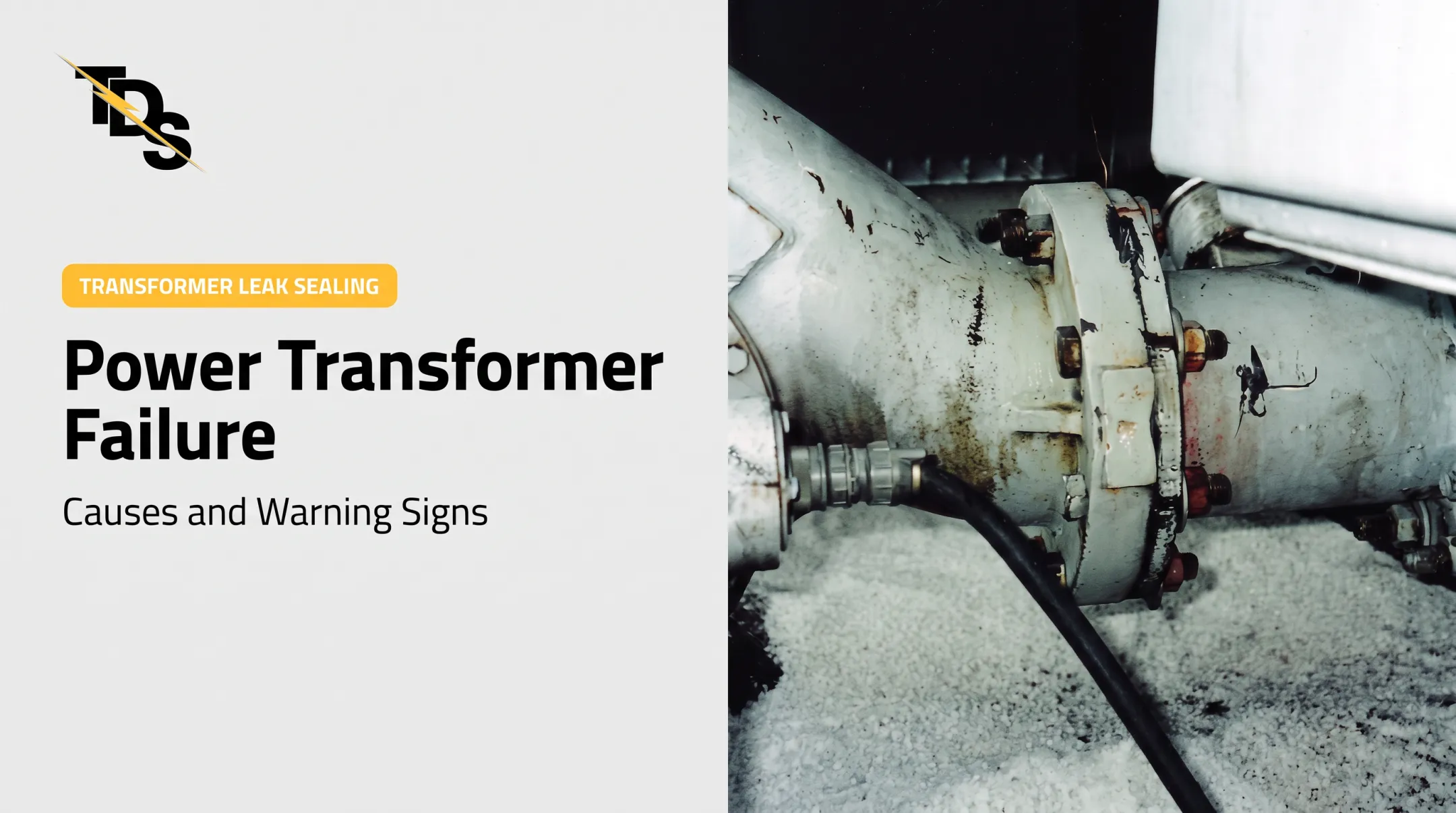
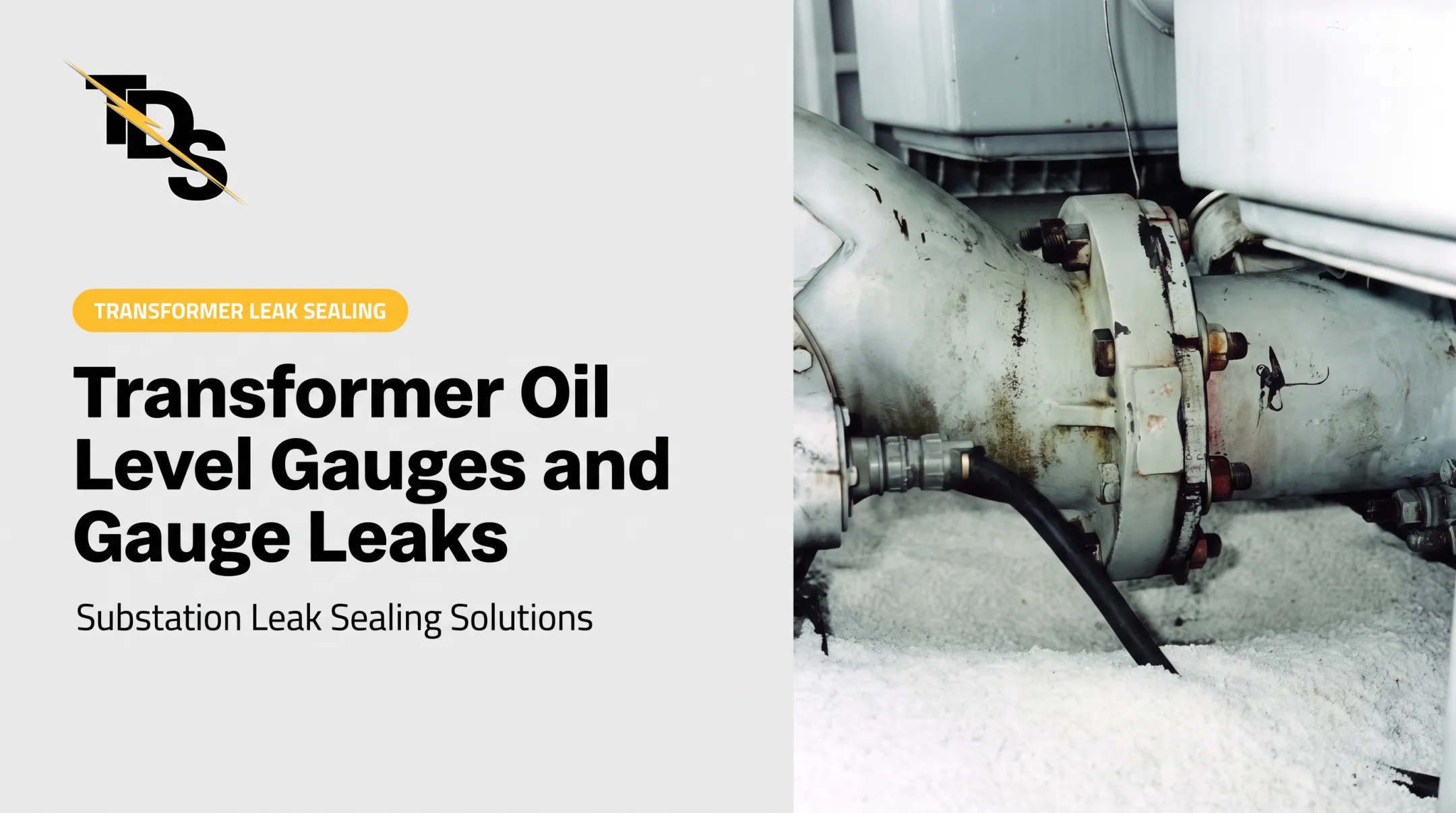
In one documented case, a temperature probe leaked from a four-bolt mounting flange. Probe designs vary, so check the specific probe and transformer design before choosing seal materials, torque values, replacement parts, or sealants. Oil compatibility is essential.
Signs of a leak
- Oil wetness, residue, staining, or dirt buildup at a fitting
- Active dripping
- Falling oil level or repeated top-offs
- Unexpected pressure behavior
- Stuck, erratic, or implausible readings, which may point to the gauge, capillary, wiring, or contacts rather than a thermal problem
Why a small leak still matters
Oil loss reduces insulation and cooling performance and opens the door to moisture, oxygen, and contamination. Thermal expansion, vibration, and load swings can enlarge a minor leak.
Low oil can also interfere with radiator circulation. In one documented scan, oil sat below the upper radiator inlet pipe, blocking circulation, while the level indicator was defective and stuck at normal. Check conclusions against the transformer design and operating instructions.
How to Troubleshoot a Gauge Reading or Probe Leak
Start with operating conditions and trends
Compare the current temperature with load, ambient temperature, fan or pump status, season, time of day, and recent history. Then compare OTI, WTI, oil-level, pressure, control-room, and remote indications. One abnormal signal among agreeing ones often points to an instrument or circuit problem.
Reclamation's FIST 3-31 diagnostics guide describes WTI reading roughly 15°C above top-oil in that practice. Treat that as a reference, not a calibration spec.
Inspect safely and document
Inspect these points for oil migration:
- Dial, lens, and pointer movement
- Capillary, wiring, and conduit
- Probe entry, pocket, and gaskets
- Flanges, tank surface, and radiator connections
Document photos, readings, load, ambient conditions, alarm status, oil level, pressure behavior, and leak location. Don't touch or disturb a possibly pressurized or energized assembly.
Separate leak, gauge fault, and overheating
Qualified technicians can use approved test methods, redundant instruments, infrared inspection, contact checks, and calibrated references. Reclamation's older guidance suggests testing thermometers every 3 to 5 years and replacing one that differs more than 5°C from a reference. That is dated guidance, not a current universal standard.
To confirm an active leak:
- Clean the area.
- Apply a compatible leak-detection method, following site safety rules.
- Watch for fresh oil.

For preliminary screening, TDS's oil leak detector spray and transformer cleaner are options. The spray goes on as a light coating, and leaking oil darkens the powder at the failed gasket or packing. These are not substitutes for qualified diagnosis, containment, or repair.
Know when to escalate
Escalate for:
- Rapidly rising temperature
- Low-level or pressure alarms
- Active dripping or oil reaching electrical components
- Persistent zero pressure where pressure should exist
- Smoke, unusual noise, or evidence of an internal fault
- Conflicting protection signals
Follow emergency response, switching, lockout/tagout, arc-flash, spill-control, and environmental procedures. Never continue operation just because a leak looks small. Reclamation also says not to re-energize after a pressure-relief device operates until testing finds and corrects the cause.
Record findings for the repair decision
Capture what a specialist needs to decide the repair path:
- Transformer make, model, age, and fluid type
- Gauge and probe details
- Leak location and photos
- Operating state, load, and temperature history
- Alarm behavior, access limits, and outage constraints
Note whether the leak is at a replaceable gauge interface, gasketed joint, damaged pocket, cracked weld, corroded area, or internal component. The location sets the repair path.
Repair, Safety, and Leak Prevention
Plan around the hazards
Probe removal, seal replacement, oil handling, pressure relief, and gauge testing demand qualified personnel, approved switching and isolation, proper PPE, and site arc-flash and environmental controls. OSHA 1910.269 requires qualified employees and arc-hazard assessment for work on or near exposed energized equipment.
Don't loosen a probe, cap, or fitting just to "check" the leak. The work plan must address internal pressure, containment, contamination control, and possible de-energization.
Choose the least disruptive repair
- Gauge or sensing assembly: replace when damaged, leaking fill fluid, or out of tolerance.
- Gasket or fitting: may be repairable.
- Tank damage, severe corrosion, internal contamination, or overheating: needs a broader outage or teardown assessment.
For compatible external leaks, TDS offers low-pressure leak sealing. TDS surveys document the equipment, leak location, repair price, and method. The repair seals only the leaking component.
Conventional repair means de-energizing, grounding, draining oil, and disassembly. Many TDS repairs can proceed with equipment energized when access to energized components is unnecessary.
For a leaking probe-well flange gasket, the documented technique drills and taps four access holes and injects sealant into the gasket groove. TDS reviews a photo of the exact component before recommending a technique. Extra bolt tightening rarely cures a failed gasket.

TDS backs leak-seal repairs with a four-year warranty. No outcome is guaranteed until the survey confirms leak location, access, materials, and operating conditions.
Verify and prevent recurrence
After any repair, check:
- Leak recurrence and oil level
- Pressure behavior and gauge response
- Alarm and trip contacts, cooling operation, and remote signals
- Any required oil or insulation testing
Set inspection intervals from the OEM manual and facility program. Eaton's substation manual, for example, schedules annual checks of gauges, fluid level, and tank pressure.
Add checks after heavy loading, transport, severe weather, or work near the gauge. Replace damaged or obsolete gauges with units matched to sensing range, mounting, seal materials, enclosure, contacts, and control requirements.
Frequently Asked Questions
What temperature should a transformer run at?
It depends on the nameplate rating, insulation system, load, ambient temperature, cooling class, and OEM alarm settings. No universal value applies.
What are the common causes of transformer overheating?
Overloading, failed or blocked cooling, low or degraded oil, restricted circulation, high ambient conditions, poor connections, internal faults, and inaccurate instrumentation.
How to prevent flux leakage in a transformer?
Magnetic flux leakage differs from an oil leak at a probe. Prevention rests on sound design, assembly, shielding, winding condition, grounding, and OEM maintenance practices.
What are two types of temperature gauges?
The Oil Temperature Indicator reads top-oil temperature. The Winding Temperature Indicator estimates winding hot-spot temperature. Terminology and construction vary by design.
What causes a transformer temperature probe to leak?
Deteriorated seals, loose or damaged fittings, thermal cycling, vibration, corrosion, impact, improper installation, and damage to the pocket or probe interface.
How can you tell if a transformer temperature gauge is faulty?
Look for a stuck or erratic pointer, readings inconsistent with load and ambient conditions, disagreement with redundant instruments, damaged capillaries or wiring, moisture in the dial, and failed contacts.