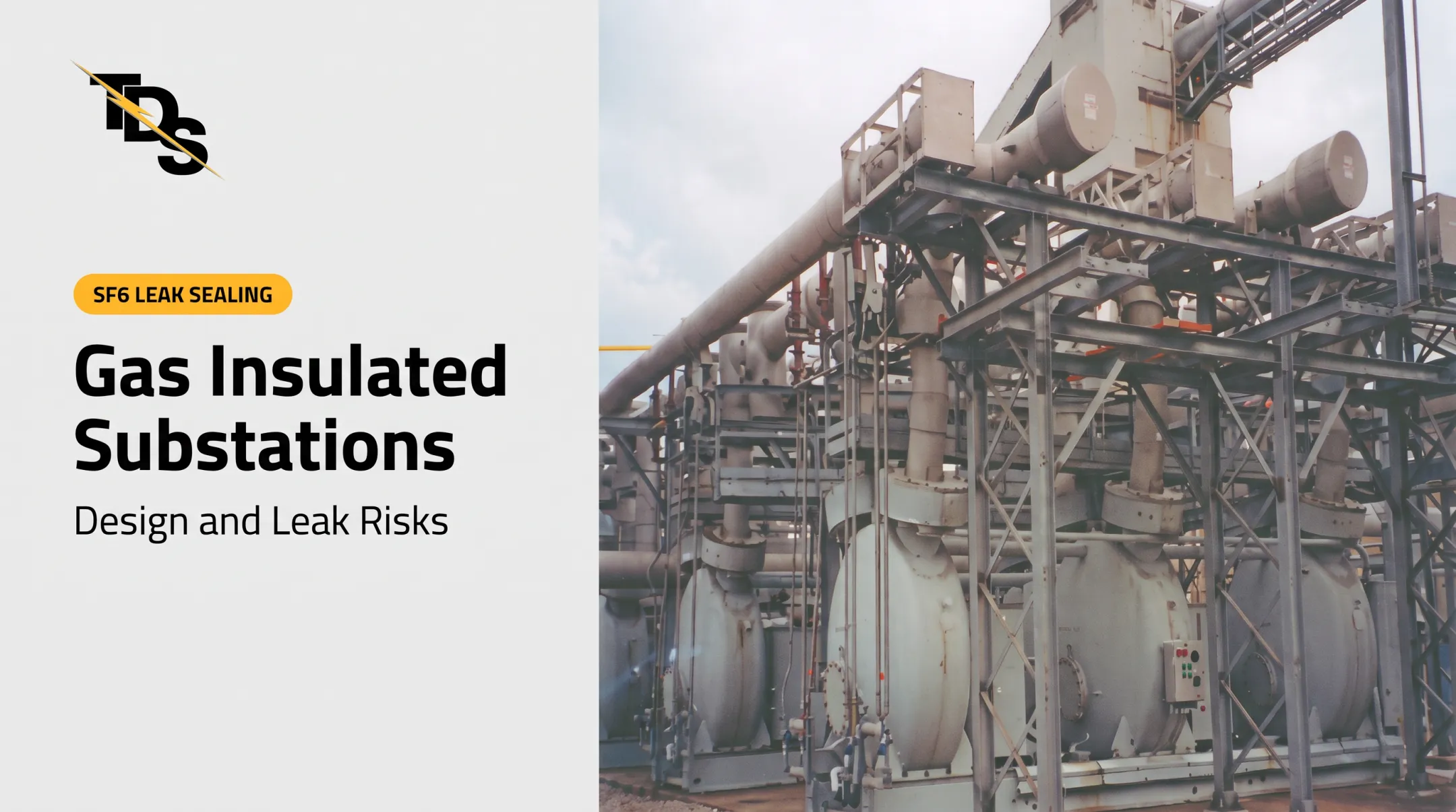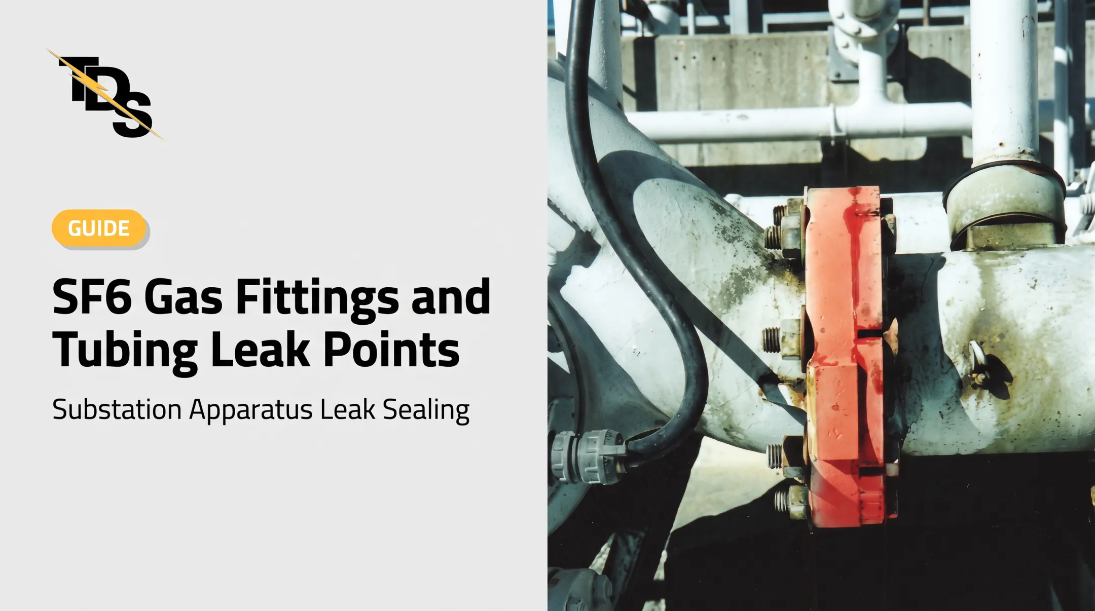

This guide is for utility, generating-plant, and substation maintenance professionals who manage oil-filled and SF6-filled dead tank equipment. It moves from construction to common leak points, then to diagnosis and repair planning. Every repair decision must be checked against OEM instructions and site safety procedures.
Key Takeaways
- A dead tank breaker houses the interrupter in a grounded metal tank, with energized conductors passing through insulated bushings.
- Likely leak sites include bushing and CT interfaces, flanges, covers, valves, density monitors, welds, and corroded areas.
- A stain, pressure change, or SF6 alarm tells you to investigate, not where the leak is.
- Confirm the source before choosing a seal, part, outage plan, or repair method.
What Is a Dead Tank Circuit Breaker?
How the "dead tank" designation is defined
In a dead tank design, the interrupter and its housing sit at ground potential. Current enters and leaves through insulated bushings. Siemens describes the contrast with a live tank breaker, whose interrupter is not grounded in service and is exposed to line voltage.
Main components in the assembly
Layouts vary by OEM and voltage class, but most units include:
- Grounded tank
- Interrupter
- Bushings
- Bushing-mounted or integral current transformers
- Insulating oil or SF6
- Gas or oil connections
- Density or pressure monitors
- Operating mechanism
Siemens documents weatherproof CT housings at the base of the bushings on both sides of each pole, a layout feature specific to dead tank designs.
Why the enclosure matters for leak analysis
The tank forms a contained fluid boundary with many mechanical interfaces. Grounding improves access and protection in some applications, but it does not make the assembly leak-proof.
Dead Tank Design: Where Sealing Interfaces Are Created
Map the sealed boundary first
Before inspecting, use the OEM assembly drawing, nameplate, and compartment layout to learn which spaces hold SF6, insulating oil, hydraulic fluid, or no pressurized fluid. Diagnosing without that map invites wasted effort on the wrong compartment.
Bushing-to-tank and flange interfaces
Bushing mounting flanges, gaskets, O-rings, compression surfaces, and hardware matter most where energized conductors pass through the grounded tank. A public JEA specification calls for a gasket or O-ring at the bushing-to-tank interface, plus RTV silicone along the bushing flanges to limit SF6 loss. That is one utility's requirement, not a universal OEM rule.
TDS reports that SF6 breaker leaks typically occur between the porcelain and base mounting flange, or at bushing end caps.
Integral CT and bushing interfaces
Dead tank designs may place CTs around or within bushing assemblies. That adds seals and connections. Exact arrangement and serviceability depend on the breaker design, so check the OEM manual.
Tank flanges, covers, and inspection openings
Bolted tank joints, manways, and inspection covers leak when gaskets age, bolt loads drift, or earlier maintenance left a poor seat. Thermal cycling and vibration make it worse. Mitsubishi's SFMT manual documents O-rings in grooves at bolted gas-sealing joints, with sealant outside the groove to limit corrosion.

Valves, monitors, fittings, and welds
Inspect these by equipment, not by assumption:
- Gas fill and recovery valves
- Density monitors and pressure fittings
- Drain and sampling points
- Relief-device interfaces, where fitted
- Tank welds and corrosion-thinned areas
Common Leak Points and What Causes Them
Oil leaks versus SF6 leaks
Oil leaves wetness, staining, or residue. SF6 often leaves nothing visible and shows up as density or pressure drift, alarms, inventory shortfalls, or detector readings. Neither symptom confirms the source.
Where leaks show up in the data
An EPA-hosted study of closed-pressure breakers found these reported leak locations:
- Gas mechanisms: 73%
- Worn or broken bushings: 21%
- Gas tanks: 6%
The data is historical (1998–2005) and not specific to dead tank designs, so use it to frame priorities, not as a current baseline.

Common causes
- Aging seals: hardening, compression set, cracking, and chemical attack. TDS notes that original gaskets can reach end of life, and that defective material or poor installation causes early failure.
- Wrong material: one elastomer compound listed as compatible with mineral oil does not prove SF6 compatibility. Verify against the OEM specification.
- Fasteners and joints: uneven compression, wrong torque, loosened hardware, flange distortion, and repeated expansion.
- Corrosion and weld damage: coating failure, pitting, impact damage, and weld defects. Pressure-boundary damage needs engineering review, not an external seal.
- Accessories: valve seats, threaded caps, instrument fittings, and hose adapters should be checked separately from the tank body.
Misleading indications
Oil migrates along tank and bushing surfaces. Old residue can linger after a repair. Temperature swings can make pressure changes look like a worsening gas leak. Clean the suspect area, trace it, and recheck.
How to Detect and Prioritize a Dead Tank Leak
Set a safe work plan
Only qualified personnel should inspect or service the equipment, following the OEM manual, site switching and clearance procedures, and approved SF6 and oil-handling practices.
OSHA 1910.269 requires qualified employees for work on exposed energized equipment. Do not treat energized inspection or repair as universally appropriate.
Record conditions first
Before disturbing anything, document:
- Breaker model, compartment, fluid type, and nameplate data
- Recent maintenance and top-off or refill history
- Temperature, pressure or density readings, and alarms
- Visible residue, with photographs
Localize the leak
Common options include:
- Visual inspection after controlled cleaning
- Approved SF6 detectors and fluid-specific methods
- Infrared optical gas imaging
EPA-hosted material documents infrared demonstrations on bushing leaks of 138 kV and 220 kV breakers. Soap-solution testing, handheld detectors, and ultrasonic devices can be thrown off by wind, noise, or survey thoroughness. TDS prefers an infrared laser-scanning unit that records SF6 as black smoke on video. Confirm any method against current OEM and industry guidance.
Confirm the source, then prioritize
Compare readings across compartments, check neighboring interfaces, and allow for fluid migration and ambient temperature. Repeat detection after cleaning when safe and permitted.

Then rank the repair by:
- Rate or severity of loss
- Proximity to energized interfaces
- Environmental exposure and reporting obligations
- Equipment criticality and alarm or lockout risk
- Structural condition
- Outage or replacement availability
US environmental and documentation duties
SF6 is a potent greenhouse gas. Under EPA's Greenhouse Gas Reporting Program, Subpart DD covers SF6 emissions from electric power system equipment, including circuit breakers. Applicability is tied to the general 25,000 metric tons CO2e threshold.
State rules differ. California and New York set phaseout dates for gas-insulated equipment, and Massachusetts sets a 1% annual leak-rate limit for gas-insulated switchgear. Check whether a standalone dead tank breaker falls inside each rule's definitions, and follow IEEE C37.122.3 and IEC 62271-4 for handling and recovery.
Repair Options and Long-Term Leak Management
Match the remedy to the confirmed source
Options range from external seal treatment, valve or monitor replacement, and gasket replacement to bushing or flange work, tank or weld repair, and full replacement. Gas recovery, fluid containment, crane access, outage planning, and OEM approval can all change the scope.
The evidence on external sealants is thin. EPRI documented a resin-based external seal on a 230 kV dead tank breaker bushing leak estimated at 300-500 kg per year, and the leak was no longer detectable at the treated area. EPRI said follow-up across large temperature changes still needed evaluation. Treat it as a demonstration, not a universal repair.
Consider low-pressure leak sealing
For compatible oil-filled or SF6-filled breakers, low-pressure sealing is worth evaluating once a survey confirms access, material compatibility, leak location, and site conditions. Transmission & Distribution Services (TDS) offers this:
- Cured-in-place gaskets replacing OEM gasket material without disassembly
- Removable enclosures or clamps filled with rubber-based sealant, such as a two-piece clamp at a porcelain-to-flange joint (about four hours, sealant cure around 20 minutes at 70°F)
- Sealant stated not to react with transformer oil or SF6
- Free equipment surveys listing equipment, leak location, repair method, and price
- A stated four-year leak-seal warranty (confirm current terms before relying on it)
TDS says it fixes only what is leaking, after confirming the exact source, and that many repairs can proceed with equipment in service. An outage may still be needed for clearance. Get OEM and engineering sign-off first.
Verify and keep a trend record
Close out each repair with:
- Post-repair leak verification
- Restored pressure or density checks
- Visual reinspection
- Updated gas or oil inventory records
- Photographs and work documentation
- A follow-up trend plan
Early detection and accurate records often matter as much as the original breaker configuration.
Frequently Asked Questions
What is a dead tank circuit breaker?
Its interrupter sits in a metal tank held at ground potential. Energized conductors enter and exit through insulated bushings.
What is the difference between dead tank and live tank circuit breakers?
A dead tank interrupter and housing are grounded, and CTs are commonly bushing-mounted. A live tank interrupter sits at line potential, which changes layout, installation, and maintenance tradeoffs.
What are the most common leak points on a dead tank circuit breaker?
Bushing and CT interfaces, tank flanges, access covers, valves, density monitors, fittings, welds, and corroded areas. OEM design determines the exact points.
How do you detect an SF6 leak in a dead tank circuit breaker?
Watch density or pressure trends and alarms, then localize with approved detectors or infrared imaging and inspect interfaces. Qualified personnel should confirm the source.
Can a dead tank circuit breaker leak oil or SF6?
Yes, depending on its insulation and interruption design. Oil and SF6 each need different detection, containment, handling, and repair procedures.