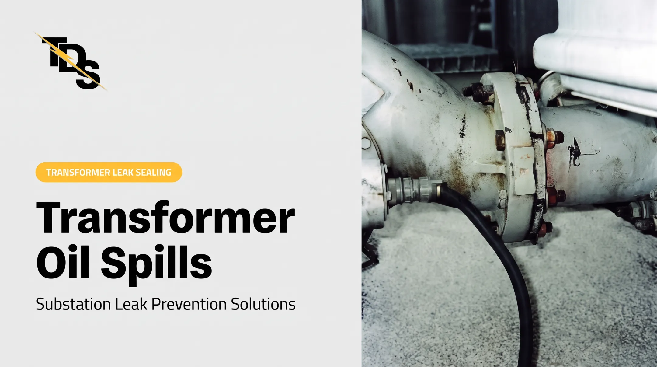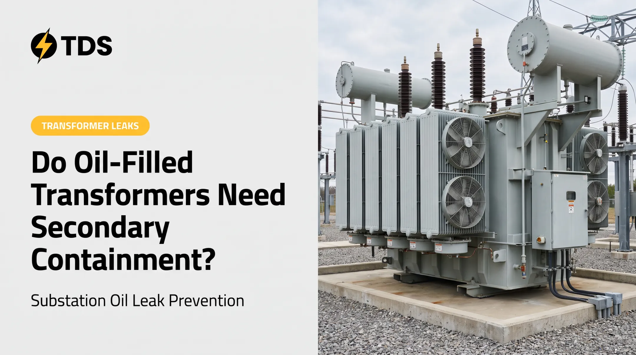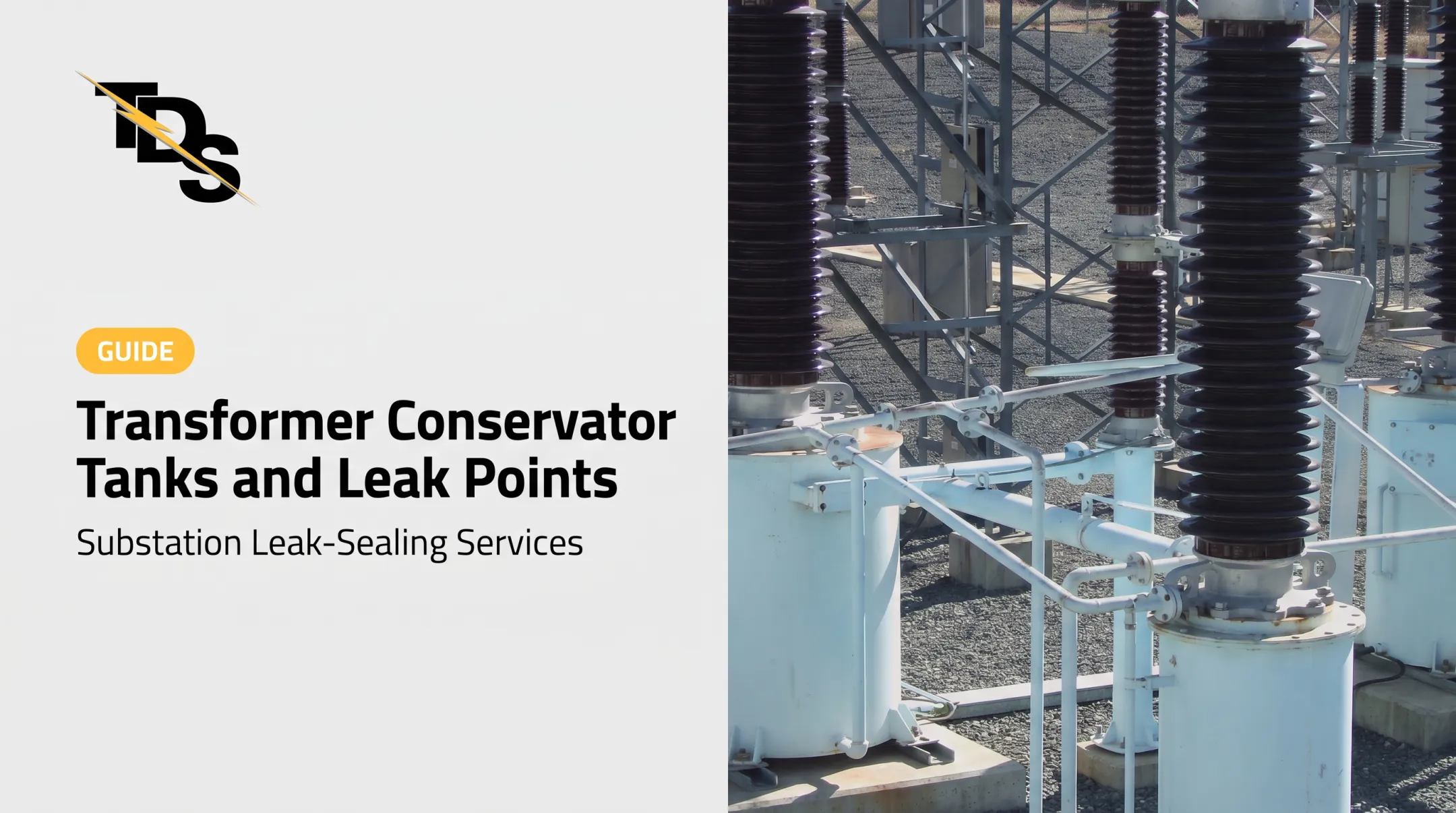

For utilities, cooperatives, generating plants, and contractors, the question is what happens to that oil once it leaves the tank. Containment has to protect soil and water, support US environmental compliance, and work around energized equipment, rain, and snowmelt.
This guide defines secondary containment, walks through SPCC planning and capacity factors, compares system types, and covers inspection and leak response.
Key Takeaways
- Containment limits the consequences of a release; it does not replace inspection, repair, or a spill plan.
- Capacity depends on the likely discharge, precipitation, displaced volume, drainage, and site conditions.
- Pits, sumps, separators, berms, liners, and ponds each fail in different ways.
- A system is only as dependable as its inspections, records, and trained people.
What Is Transformer Secondary Oil Containment and Why Does It Matter?
Primary vs. Secondary Containment
The transformer tank, bushings, radiators, valves, and seals are the primary barrier holding the oil. Secondary containment is the engineered basin, vault, liner, berm, sump, drainage control, or filtration arrangement that catches what escapes.
A complete system keeps released oil away from soil, groundwater, storm drains, surface water, and neighboring property. It also has to handle ordinary rainwater and snowmelt without becoming a liability.
Why Transformer Sites Are Hard
Transformer sites bring a particular set of constraints:
- Large oil inventories in a single unit
- Outdoor exposure to weather
- Unmanned or remotely monitored substations
- Tight footprints, grounding grids, and cable runs
- Fire concerns and the need to preserve electrical clearances
What Containment Does Not Do
Containment is not fire protection, oil filtration, or leak repair. IEEE 980-2021 covers oil-spill containment in substations, while IEEE 979 addresses substation fire protection separately. Oil-condition standards such as IEC 60422 govern monitoring and maintenance of the oil itself. One feature rarely covers every risk.
What an Uncontrolled Release Costs
A 1998 transformer failure at Allegheny Power's Belmont Substation released about 19,000 gallons of oil into two tributaries of Cow Creek. According to EPA's settlement record, costs included:
- Roughly $450,000 on containment and cleanup
- About $6.9 million replacing three large transformers, two of them undamaged
- A $252,000 penalty plus commitments to added safeguards
These figures describe one case, not an industry average.
US Regulatory and Capacity Planning Considerations
How SPCC Applies
The federal Spill Prevention, Control, and Countermeasure (SPCC) rule, 40 CFR Part 112, applies to non-transportation facilities where an oil discharge to navigable waters or shorelines is reasonably foreseeable. The aboveground threshold is more than 1,320 gallons in aggregate, counting only containers of 55 gallons or more. EPA confirms that oil-filled electrical equipment such as transformers counts toward that total.

Transformers are classed as oil-filled operational equipment (OOOE), not bulk storage containers. That distinction matters for sizing:
- Section 112.7(c) requires appropriate containment or diversion, sized for the typical failure mode and most likely discharge.
- The "largest container plus freeboard" rule in 112.8(c)(2) applies to bulk storage, not automatically to transformers.
- EPA's 25-year, 24-hour storm figure is guidance for bulk storage freeboard, not a codified transformer requirement.
The OOOE Alternative
Qualifying OOOE can skip general secondary containment under 112.7(k) if the facility has:
- No single discharge over 1,000 gallons
- No two discharges over 42 gallons each in any 12-month period during the prior three years
The plan must then document inspection and monitoring, plus a contingency plan and a written commitment of personnel, equipment, and materials.
Capacity and Site Inputs
Capacity work typically accounts for:
- The largest credible release and any shared containment
- Precipitation or snowmelt and freeboard (NOAA Atlas 14 supplies location-specific rainfall data)
- Volume displaced by pads, piers, stone, and equipment
- Topography, soil permeability, groundwater, and drainage paths
- Fences, roads, gates, underground utilities, and grounding systems
- Emergency access and future equipment changes
Documentation and Responsibility
Key SPCC documentation requirements include:
- Keep written inspection procedures and signed records with the plan for three years
- Train oil-handling personnel on discharge prevention, with briefings at least annually
- Review the plan every five years and amend it within six months of material changes
SPCC duty attaches to the facility owner or operator, so transformer title alone does not settle who is responsible when a utility and a customer share a site.
State and local rules add another layer. California's APSA, New York's petroleum bulk storage program, and industrial stormwater permits each treat transformers differently. Have a qualified environmental professional, and a professional engineer where required, review the plan.
Types of Transformer Secondary Oil Containment Systems
Pits, Pools, Vaults, and Sumps
Concrete pits hold large releases well. Their weak points are rainwater accumulation, pumping needs, sediment, cracks, pipe and cable penetrations, and vegetation growth.
Separators, Pumps, and Valves
Oil-water separators, dewatering pumps, oil-sensing pumps, and oil-stop valves manage stormwater while retaining oil. Flow-rate design must match the site, and sensors, floats, and relays can fail.
The Allegheny consent decree, for instance, required sump pumps around transformer pits that shut off on a transformer fault, plus drain valves restricting oil leaving the substation. That is a site-specific remedy, not a design standard.
Passive Filter Media
Passive media let water pass while retaining hydrocarbons. Independent performance and clogging data for transformer basins is hard to find in public sources. Demand validated test results, replacement intervals, and inspection access before specifying any product.
Berms, Walls, and Liners
Above-grade berms, fiberglass or concrete walls, geomembrane liners, and sealed areas all depend on construction quality.
EPA's 1996 liner study noted sun and weather degradation, cracking, and animal or vandal damage to exposed liners, and stressed inspection and prompt repair. Penetrations, settlement, and abrasion are common weak points.
Retention Ponds
Ponds suit sites with land to spare. Evaluate hydraulic capacity, water quality, emergency access, and long-term maintenance. Wildlife is a real concern: a 2001 Fish and Wildlife Service case documented dozens of waterfowl killed at an oil pit.
Choosing a System
Weigh these factors together:
- Oil volume and transformer arrangement
- Climate and precipitation
- Soil and groundwater
- Available space and expected staffing
- Fire strategy and discharge pathway
- Lifecycle cost and the approved SPCC plan
How to Design, Inspect, and Maintain a System
Pre-Design Checklist
- Confirm transformer oil inventory and containment boundaries.
- Locate low points and drainage outlets.
- Map pipe and cable penetrations, liner seams, and wall joints.
- Coordinate fire controls, access routes, signage, and emergency equipment.

Routine Inspection Points
- Cracks, settlement, and corrosion
- Damaged liners and failed seals
- Blocked filters and sediment
- Vegetation and standing water
- Drain-valve position
- Pump and alarm operation
- Oil sheen and signs of past overflow
Dewatering and Stormwater
Inspect collected water before discharge and follow the approved procedure. Keep these rules absolute:
- Never pump oil to a drain
- Document recovered oil and waste
- Never assume an unattended valve or filter still works
Frequency and Reassessment
No single federal interval covers every transformer. Set frequency through the SPCC plan, manufacturer instructions, site risk, and weather exposure. Reassess after:
- Transformer replacement or oil changes
- Construction, or changes in grading or drainage
- Extreme weather, a spill, or a near miss
Record findings and track corrective actions to closure.
Preventing and Responding to Transformer Oil Leaks
Source Control
EPRI's maintenance guide lists common leak points:
- Gasket joints and welds
- Gas-relay piping and valve packing
- CT pockets and tap changers
- Radiators, main-tank covers, and bushings
Check these for seepage, cracking, and rust, and document recurring weeps promptly. EPA inspections can examine whether leaks are documented and whether an action plan exists.
Immediate Response
- Protect personnel and follow switching and electrical-safety procedures (OSHA 1910.269 applies to this work).
- Stop the source only when it is safe.
- Protect nearby drains and waterways.
- Activate the site spill plan.
- Notify required parties. Report any discharge that causes a sheen on water to the National Response Center immediately.
- Preserve evidence for reporting and corrective action.

A separate SPCC report to the EPA Regional Administrator is due within 60 days after a single discharge over 1,000 gallons, or two discharges over 42 gallons in 12 months.
Where Leak Sealing Fits
Transmission & Distribution Services (TDS) offers leak sealing as a complement to containment, not a substitute. Its technicians work only in substations, using a low-pressure, cured-in-place sealant method that replaces failed gasket material without traditional disassembly.
Where conditions allow, that approach can cut teardown and downtime. A 4-bolt flange can usually be repaired in about two hours without draining the oil.
TDS also offers free equipment surveys that document and photograph each leak, with repair method, itemized cost, and outage requirements. Repairs carry a four-year warranty. Not every repair can be done energized; upper leaks near bushings may require de-energizing, so site assessment and qualified personnel come first. TDS does not install containment systems.
Frequently Asked Questions
What is the IEC standard for transformer oil filtration?
IEC standards address oil condition, not spill containment. IEC 60422 covers oil supervision and maintenance, IEC 60296 covers oil specifications, and IEC 60475 covers sampling. Confirm the current edition with IEC.
What are the containment requirements for oil storage?
They depend on oil quantity, equipment classification, facility operations, SPCC applicability, and state or local rules. Follow your approved facility plan and consult qualified environmental or engineering professionals.
How can you tell if a transformer is oil filled?
Check the nameplate, manufacturer documentation, oil-level indicators, radiator or conservator arrangements, and inspection records. Qualified personnel should confirm equipment status.
How much oil should a transformer secondary containment system hold?
Capacity comes from the applicable regulatory and engineering basis, typically the largest credible release, precipitation or snowmelt, displaced volume, shared equipment, and drainage. No single formula fits every transformer.
How often should transformer oil containment be inspected?
Follow the SPCC plan, manufacturer guidance, site risk, and applicable regulations. Add checks after severe weather, maintenance, spills, or system changes.